


Application templates are a time-savings teaching tool that offers:


Heath: All right, everyone. Welcome to another Losant Deeper Dive. My name is Heath, your host for this webinar. Thank you all for being here. I really think we've got a great Deeper Dive planned for you today. We're going to be taking a closer look at how you can deploy low-code IoT solutions from the cloud to your embedded devices with the Losant Embedded Edge Agent. Today I'm joined by Losant's own chief product officer, Brandon Cannaday, who's going to walk us through not only some high-level concepts about the Embedded Edge Agent, but also some very low-level stuff, talking about the device he's working with and some other things. Before we go any further, I do want to provide a couple bits of info on this webinar. This webinar is being recorded so that we can make the replay available to you in a few different ways. We're going to send you an email with a link to the replay, and the recording will also be made available on Losant's YouTube page, as well as on our Deeper Dive page on our website. Now, we'd love hearing your questions. So I would like to point out a few key features here in the Zoom conference. You can use the Q&A feature or the Chat feature to pose questions, and I, myself, would be monitoring those throughout our time together. Then, at the end, I'll moderate a quick Q&A session with those posted questions. [Coughs] Excuse me. Let's do a quick review of the Losant Enterprise IoT Platform. Losant is an industry-leading IoT platform. As an application enablement platform, Losant provides enterprises with the building blocks they need to create their own IoT products. The Losant Platform consists of five key integrated components to help customers achieve that. First, End-User Experiences, which allow you to build a fully functional web interface that lets your users interact with your connected devices. A Visual Workflow Engine, which is the low-code brains of your connected solution is how you trigger email notifications, create events, send commands to connect to devices, and much more. Data Visualization, which also includes integration with Jupyter Notebooks, allows you and your end-users to see what your connected devices are doing. Devices and Data Sources allow you to create a digital twin of your devices in the field, as well as integrate with other services that have the data you care about. Finally, Edge Compute. What we're going to be taking a closer look at today is this suite of functionality that enables you to execute business logic right at the Edge. Our customers and partners utilize all five of these integrated components to create a robust IoT product that they can put in front of their end-users. Losant is a leader in the industrial telecommunications and smart environment spaces, and we've also got a platform for all sorts of customers, ranging from startups to companies in the Fortune 100. If you're interested in learning more, please reach out, and we will be happy to set up some time for you to have a more in-depth conversation about how Losant can help you develop a connected solution. While Losant provides a software foundation for IoT, we've surrounded ourselves with a great ecosystem of partners that helped create this IoT solution. This includes strategic partners that we share go-to-market strategies with, service partners who work with you to develop your end-to-end IoT applications, and the technology partners that provide hardware connectivity and other services to round out your IoT solution. Again, I couldn't be more excited to have y'all here today. I'm going to pass this virtual mic to Brandon to get us started. Again, if you have any questions, please don't hesitate to put those in the Q&A and Chat, and we'll do that Q&A at the end of our session. Brandon.
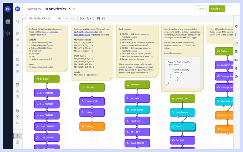
Brandon: All right. Thanks, Heath. I am really excited to cover this topic. I've been a fan of the ESP32 for a long time, and being able to use some Losant workflows to control it has been a really fun and interesting project. So, once again, my name is Brandon Cannaday, and I am going to be talking about using Losant's Embedded Edge Agent to remotely control and monitor a bunch of IO that's attached to ESP32 devices. A little bit of recap with the Embedded Edge Agent is fairly new introduction to Losant, but long story short, it brings our Visual Workflow Engine to much smaller resource-constrained devices and gateways, including in this Deeper Dive, the ESP32. Our main goal, especially for product managers that are joining us today is really to help you get connected products out the door, into the hands of your customers as fast as possible. You want to focus on the far right-hand side of this graph. Those perfectly tailored, we call them IoT products or end-user experiences, it's delivering the thing that's going to add revenue and expand your product portfolio. For the developers on this Deeper Dive, you know that comes with a lot of challenges, and that's really what the EEA and ESP32 are here to solve. We want to really bring that speed and agility of low code into modules like the ESP32. Even if you're not considering that specific module, a lot of lessons and concepts that I am applying or we'll be covering today will apply to almost any module. For the ESP32 specifically, it does act as a really good primary module to a wide variety of IoT products. You could want to picture in your head the stuff on the left-hand side. They could be battery-powered sensors, maybe new controllers, perhaps devices that are designed to monitor equipment, something like Modbus. ESP32 does come with a built-in Modbus client. It's a great module for asset tracking, asset monitoring. So as I'm going through this, you can think about, "Well, what are the use cases for an IoT product? What are my customers looking for? How can the EEA solve that middle ground around accelerating all of that firmware development at the Edge?" Everything I'm going to show today is available as part of our ESP32 and EEA application template. So just like with all of our other application templates, any Losant developer, even using our no-cost Developer Sandbox can go in. When you create a new application, you'll be presented with the screen on the left. If you choose that template, all the workflows, dashboards, and the device model will be created for you, so you can explore everything I'm going to cover in detail by using that application template. Before I'm going to get too deep, let's actually see this thing in action. So what I have on the right side of my screen is a real-time view of an ESP32 sitting next to me on a desk under this camera. Right now, it's just blinking the onboard LED, but I've got a lot of other IO connected to this as well. So I'm using the ESP32-WROVER kit. This is a really nice developer kit for anyone new who wants to explore the ESP32. It's got a lot of IO, it's got the onboard RGB LED. That way, you can explore the EEA without requiring any other hardware. What I've attached to it are some external LEDs on three digital outputs. I've got a magnetic contact switch as a digital input, and then off-screen, that's inside the plan is one of these moisture sensors acting as an analog input. So if I switch to the Losant dashboard, we can see that this template comes with a dashboard that understands the IO connected to this specific board. We've got the moisture sensor value down here and historically over time, seal's watered recently, and now that that level's slowly decreasing. The contact switch, real-time value here. So if I actually grab the contact switch and move it away, we can see the value of that block change in almost real-time. Well, we've also got an input controls block. So the Embedded Workflow that I've got deployed to this device to this device understands a few device commands. Check out Losant's documentation for more information about device commands, but our platform does support bi-directional communication, not only reporting [Inaudible 00:08:43] data up like the moisture and the contact switch, but also sending commands down so the device can take action. In this case, I've got the blinking LED. I'll highlight that in case it's hard to see. The onboard blinking LED is here. I can turn that off, tell it to stop blinking automatically, and now it's just on. Then I could start clicking this toggle button manually control it. I've also got three toggle switches here where I can manually control the state of all three external LEDs. What's happening behind the scenes is I'm sending commands to this workflow, and the workflow is what's taking action. That's really where we get into that control over the ESP32's IO. So that turned blinking back on. Let's take a quick look at the actual workflow. So once a second, this workflow is triggering and then performing some kind of action. In this case, it's determining whether or not the automatic blinking should happen. It's toggling the value between zero and one, and then setting the state of each of those digital outputs. Later in this tutorial, after I get through some of the firmware side of this, I'll take a very close look at what's going on. I just wanted to provide a high level of review right now. If I return to that dashboard and turn blinking off, we can come back and we can see what has happened is this device just received the blink command, which instructs it to turn off that automatic blinking. I then go back and manually toggle that LED, returning to the dashboard, and we can see that now that manual toggle is [Inaudible 00:10:19]. It's connected to the same nodes as the timer. It's just toggling it manually with the toggle command instead of automatically. So what I'm looking at here is called the Losant live look. So this is supported in both Gateway Edge Agent and the Embedded Edge Agent. Losant's had the Gateway Edge Agent for a long time, that runs on a Linux capable, more larger [Inaudible 00:10:41] gateway, so ship it as a Docker container. That's going to be a really good fit if you've got some off-the-shelf equipment, you've got a larger gateway, but both of them do this live look whenever a Debug Node is hit, streams that debugger information to the cloud so you can remotely view what's going on with your workflows, really from anywhere in the world, on any fielded piece of equipment. So let's take a moment and take a much more technical deep dive and figure out what's happening behind the scenes. How are these workflows getting to my device, in what form, and how is the device running them? Well, for Losant, we decided to use WebAssemby for this process. A lot of people might think, "Well, WebAssembly was made for the web, for browsers," and that's true. Originally, it was intended to bring high performance in portable applications to web browsers. But what the community found and what we found is the underlying specification for WebAssembly really resulted in a very portable and performant and self-contained bundle of logic. So when you design workflows in Losant and you hit Deploy, we're compiling that workflow and a Losant Agent that helps facilitate executing those workflows together into a WebAssembly bundle, and then deploying that down to the device over MQTT. So whereas we say low code, there is some code required, but it's limited. It's restricted, it's reduced. Really, the former developer's responsibility now is to implement a WebAssembly runtime, and there are open source WebAssemby runtimes in basically every language and supporting every operating system. So the word "embedded" in the Embedded Edge Agent has two meanings. First, it is designed to run on embedded devices, but also the Embedded Edge Agent is designed to be embedded inside existing edge applications. So unlike the full Gateway Edge Agent which is shipped as a Docker container, a standalone service, you just run it on a regular computer, the Embedded Edge Agent lives inside your firmware or your application. So your application could be doing all kinds of other stuff that you require it to do, but by taking one of these open source runtimes in whatever language you're choosing, and today I'm going to be showing C++, you can bring the EEA, that low code runtime, into your existing or new edge environments. So I mentioned portability a lot. WebAssembly is very portable, has no external dependencies. So when it's deployed on ESP32, it doesn't really know about the GPIO, it doesn't know how to talk over a network connection. It's very isolated. That's what allows our workflows to run on basically any piece of equipment. What's nice is the WebAssembly spec, open that here, has two concepts. One is called Exports and one is called Imports. You don't have to worry about reading this whole WebAssembly spec, but for us, we've really leveraged the ability to import and export functions. So those functions, those imports and exports here, and defined by the EEA API, which is fully documented here, really control how that native code, how that firmware can communicate between the workflows you deployed and the host application. In this case, what I'm really going to show is how do our workflows know how to control and read GPIO? It's really leveraging these imports and exports. So imported functions are functions that are defined in the native code and then executed by WebAssembly, though we really leverage that for access in GPIO. How to read an analog input, for example, is defined in the native code, and we can present that function to the WebAssembly, to our workflows, and the workflows can then invoke that whenever they're needed. So you can drag and drop, rearrange how they're invoked, but the actual code will be defined in native code. Exports go the other way. They are functions defined by Losant inside our WebAssembly module, and then your native code gets to invoke those. Most common one is probably going to be the initialized functions. So when you receive a new workflow bundle and you want to load it up, you have to call initialize, and that helps the Losant Edge Agent get stuff all figured out so that the Init function is defined in the WebAssembly module, but invoked by a native code. All the code that I'm going to show, and I'm going to switch over and look at a little bit of code, is available open-source repository, up here in the Losant's organization in Github called EEA Examples. There are examples in several languages, Python and Node, but also for the ESP32. I think Python is going to be a very popular language for the EEA, going to be great for a little more capable devices to gateways that may not be able to run Docker, but you may want to create a Python application that includes the EEA. So we've got an example there. This ESP32 one, this includes some reference or example source code. Now, I'm not going to go out and say you can use this out of the box. There are some shortcuts in here. If you've ever used ESP32, for example, they are right here. They provide this example connect function. It's really a way just to get your device connected to WiFi quickly, but not intended for production use cases. So whereas this code does provide a lot of great reference implementation, you're still going to require a little bit of work to get it up to a state where you'd want to get it into production. A couple things I want to point out if you do pick this up. The EEA does take one to two megabytes of memory, so what I'm showing the WROVER kit uses the WROVER-E module, has that external PSRAM on it. When we include the WebAssembly runtime, the MQTT library, TLS, we exceed the ESP32's default IRAM space. So there is some required configuration, and that is done using the MenuConfig tool that comes with the ESP-IDF. ESP-IDF is the officially provided development environment for the ESP32. It's called the IoT development framework, and it comes with a tool called MenuConfig. I'll bring that up. It looks like this. So, for example, when it says, "The first thing you need to do is change the compiler options," you got down to Compiler Options, optimization level, optimize for size. So when you see these items over here, that's how they map to MenuConfig. You access the MenuConfig using the menuconfig command. After installing the ESP-IDF, you'll get this tool, and that tool comes with a lot of different options. The other thing you have to do is configure the credentials. So this firmware has the device ID access key and access secret included in the firmware itself. So inside eea_config.h, you just need to include those right here. The template that we're providing, if I switch back to that template, it does have a device included right with it, called ESP32. This is what you'll use to get the device ID, and if you want to receive an access key, you can do that up here in the menu, create that access key and secret. A little pro tip here. Even though we are including the device ID directly in the firmware, a lot of on-demand provision techniques, you may not want to do that. Losant does have the ability to bulk-create devices, so if you've got a big spreadsheet of all your devices, you can bulk-create them all, or you can automatically generate a large set of these credentials. Alternatively, inside our template library, there is a set of provisioning templates underneath the provisioning folder. The one to probably look at is the Dynamic Registration. What this one does is, when you factory flash your devices, you would include some kind of unique manufacturer ID, and this template implements a secure round trip between the device and the cloud in order to dynamically create the device ID access key and secret when it's needed instead of all upfront. So this will include some changes to the ESP32 firmware in order to make this HTTP request, but all the Losant side, you can get through this template. So definitely something to check out if you want to move to a Dynamic Registration. So a little bit about this firmware. Let's check out some of its core architecture. It's all FreeRTOS. All of the ESP-IDF is implemented in FreeRTOS, and this firmware is using two main tasks. We’ve got the MQTT task, and tasks in firmware are just those loops, those infinite loops constantly pumping some kind of activity. We've got the MQTT client that's publishing and subscribing to and for messages from the platform, and then we've got the runtime or the EEA task itself. That's what wraps up the Wasm3 open-source runtime, and it's just constantly calling the loop exported function from the EEA in order to pump and execute those workflows. So what would happen here is, when a message is received from the cloud, for example, when I was sending those toggle commands the client is subscribing to the device's command topic. It's going to receive that message, and then to facilitate communication between these tasks are FreeRTOS queues. Tasks and queues are the major two items within FreeRTOS. Down here at the bottom, I've just put some... what they're called and a link to them, so you can go look those up. But a command will get published from the platform, will be received by the clients that subscribe to it, that MQTT client is going to push that message into the EEA queue, and then the EEA task when it's ready on its next loop interval, it will pull the message out of the queue and invoke the imported function EEA or exported function eea_message_received. If I switch to the Embedded Edge Agent API, we can see the message_received function is documented here. This is how your native code will push information into the EEA itself. So when that message is received from MQTT, when it pulls it out of the queue, it turns around and invokes this message, sending some information about the payload that it received. So if we go into the code itself, I'm not going to through line by line, but I do want to check or show a little bit of these queues and tasks specifically because this ESP32 is using that external RAM, and there are some gotchas if you're using the external memory with FreeRTOS. This example firmware does navigate around this. So first, you'll see here, I got my MQTT queue, and I've got my EEA queue. The flows queue, I'm not going to talk about, but it's another queue. This is what handles new workflows when they're deployed. Workflows can be quite large, so this is a queue with a larger object and a maximum size of one. Then the task I created down here, I'll get there in a minute, but the one thing to check out is that I am using xQueueCreateStatic. The static variant of this allows me to pass in the memory that's going to be used for that queue instead of it being allocated automatically. If it's allocated automatically, it's going to come from the board's main menu or main memory, and there's only 512kb of main memory, so you're going to run out of this memory pretty quickly if your MQTT messages are anywhere near the max size of Losant's support, which is 256k. Right here is the trick to make that happen. The ESP-IDF has a allocator function called heaps. heap_caps_malloc, that allows us basically capability, allows us to allocate memory specifically from a chunk of memory that's available. In this case, SPIR RAM, SPIRAM, that is the external memory. So I'm allocating capacity for 10 messages from the external memory. That gives me a buffer that then I pass to the queue. So it's a big pro tip when you pick up one of these ESP WROVERS and you're trying to access that external memory. This is something that a lot of people are going to run into. Then let's just jump into the EEA runtime and we can see how that task is allocated. All of this code... There's a lot of code in this file, but the majority of it is implementing the Wasm3 runtime. So you can look through that on your own time, or go to the Wasm3 documentation and examples and see how that's implemented. But down here is where this task is being created, and the actual task is created here. Again, I'm using the static variant of xTaskCreate, which allows me to pass in the memory, and that memory is allocated right up, here again, giving it plenty of space to load these bundles. These workflow bundles can be quite big as well, up to 256k bundle coming from the cloud. When that's unrolled, compiled, it uses a just-in-time compilation step to turn that into something that can execute, can use quite a bit of memory. So just like before, allocating that from the external memory and then passing that into the task. There are quite a few other little gotchas when it comes to using the external memory with ESP-IDF. One I'm just going to toss out as a definitely pro tip, it caught me and cost me about an hour of work to figure out what's going on, this firmware does persist all the workflow bundles it receives into NVS, non-volatile storage, and you can't write to NVS from tasks that run from external memory. It explodes in unintuitive ways, so definitely remember that if you want to read and write from NVS, you can't do that from these tasks that are allocated out of external memory, which is why there is another task that doesn't use the static variant that's just designed to persist workflow bundles. This task runs out of main memory. So keep that in mind. That's going to be a nice gotcha that can save quite bit of time. So let's see what happens... Well, there's one more file first, the main file. Everything so far I've showed is boilerplate that'll apply to pretty much any EEA implementation using ESP32. But what's inside the registered functions file, this is implementation-specific. I'm going to spend a lot of time on this file. It's very important to get this concept. Losant has something called registered functions. If I go back to the API documentation, you'll see that document down here. This is those imported functions that are defined in the native code, that our workflows can execute. It's really important to understand this API. When it comes to almost all use cases, you'll have a considerable number of registered functions to really expose that native capability, reading underlying peripherals or sensors, getting that capability into your workflows. This firmware has several that wrap the underlying GPIO functionality of the ESP32, or ESP-IDF. So I'm importing a function called gpio_set_direction, and all it does is directly call the underlying function gpio_set_direction. So I'm basically taking these lower-level functions and then implementing the way that the workflows can invoke them. Then I've got all these... I'll go through some of these as we go through these workflows, and then down here is the actual code that includes those, links those into the module. You can see, here's my module, here's my function. That's the signature of the function, and there's the function I want to call. So now with inside the workflows themselves, they can actually invoke these functions, and what it'll do is call this function instead. Really important concept. All right. Let's see what happens now when... Let's just go through the whole process when I select one of these commands and send it down. So if I come here and turn blinking back off, toggle the RGB, we'll return to here. What just happened is the command went down, picked up by the task, inserted in the queue. That command was pushed into the EEA, in the EEA Agent inside that WebAssembly module, picked up message up. It then looked around to see, "Are there any workflows that should toggle on device commands?" What I have here is a workflow that certainly does. It has two command triggers beneath each other and checking for specific commands, and then it does some actions. It's going to hit three registry functions, so what's going to continue happening is it's going to go back in the native code, do some registry functions, get some data back if it needs it. Then what's happening is, it's invoking a Debug Node. Debug Node has to send some message back to the platform in order for this debug information to happen. So that's this side. The EEA Agent, it hit a Debug Node and said, "Hey, my workflow just hit a Debug Node. It needs to send some data. I need to get some data back to the platform." So it invokes the imported eea_send_message function to go back to the API. Imported function has sent message, basically, it says, "Well, I need you, native code, to send this information back over your MQTT client to the cloud." It's going to put that back into the MQTT queue, which is going to be picked up by the client, and then published on the correct topic back to Losant. That is how this data... Oops. ...this data makes it all the way back to Losant for the live debugging. So this application template has two workflows. I'm showing the larger one, which I'll get into a little bit later, but there is just a smaller one called Blink LED. This workflow is designed to just blink the on-board LED, so it's a good place to start if you just have the WROVER kit, you haven't wired up all the other stuff to the board like I have, you can still use this template with off-the-shelf hardware. So from here, we're going to step into some of these registered functions, really take a deep dive in how this is implemented. First, we got the EEA Init trigger. This gets run whenever a new module's loaded. New modules received from the cloud or your firmware that's implementing that runtime, loading that module, then it calls the Init function. If we go back here, it's an exported function eea_init. This is the very first thing you must call after loading the Losant bundle. I do want to say our Embedded Edge Agent does have a full walkthrough. Some of the concepts, I'm skipping a little bit, just high-level WebAssembly, how do you interact with imports and exports? So I would recommend anyone new to WebAssembly to go through this walkthrough. It's using a Python runtime, but it really starts with, what is WebAssembly? How do we just load the module? We provide you, we call it a Hello World module. Implement's a very small piece of the EEA API. That way, you can start exploring, "How do I invoke imported and exported functions?" So I'd recommend doing this one. You can do this on your own computer just using Python before jumping into something as large as this ESP32 example. So the EEA Init, what is going to result is that's going to call this trigger. The agent running in there just picked up that Init was called, and it's going to invoke this trigger. What I'm doing is calling three registered functions. The onboard RGB LED is made up of three individual LEDs, a red, a green, and a blue. They're attached to the board on pins 0, 2, and 4. So if we look at the configuration for this registered function, I'm calling gpio_set_direction. As the first argument, I'm passing 0, which is the pin number, and as the second argument, I'm passing 2. Now, 2 corresponds to the actual value of these defines that the ESP-IDF provides. I've outlined them here in this table. You can see number 2 represents gpio_mode_output. So whenever the EEA is initialized, I'm setting each of these digital outputs or these digital pins as digital outputs. If you've ever worked with embedded hardware like Arduino. You have to configure the pin before you can read or write to it. So let's take a quick look at what's happening. That's calling the ESP, the registered function gpio_set_direction, Let's jump back into the registered function's code, and that is defined right here. So you'll notice all of our functions are prefixed with eea_fn. That's required in order to reduce potential conflicts. There's a lot of just functions defined in the WebAssembly module, and we don't want you to happen to import one or register one that conflicts with one that might exist. So when you define an import [Inaudible 00:33:03], import it with a prefix, but that prefix isn't required when you invoke it. So that's why you'll see here, when I do invoke it, I am not using the prefix. It's just required in the underlying infrastructure down here. When I import it, I have to import it with the name, including that special prefix. Back up to the function itself, sst_direction, if you look in here I did provide full links to all of the ESP-IDF code. You can see what function it calls. It's taking those two parameters, first one's the pin. Those two arguments, which was 0, 2, and 4 for the RGBs. The second parameter is the mode, which is 2, which means digital output, and then it directly calls an underlying function. That function is here. You go to the ESP-IDF documentation, you can see what this function is, what it requires, and that can be a bit quite helpful when defining your registered functions wherever your underlying framework might be. This is also really good use case or example of how to think about registered functions. I could have imported a function that directly registered or set the direction of pin 2. I could have called it set_direction_pin0, set_direction_pin2, but that constrains how flexible I can then be in the workflow. By directly wrapping the underlying call, I can then pass. I now can set the direction of any pin I want, any time I want, in the order I want using the workflow because I can pass at any pin and any mode. So when you're creating registered functions, really think about making these flexible, configurable, not so constrained. That allows you to potentially add capability in the field later, if somebody plugs something into your device in the field and it's on new pins, you don't want to have to deploy new registered functions. You just want to deploy new workflows to now talk to that IO. So that is the configuring our digital outputs. Now that I got three digital outputs, 0, 2, and 4, I can start controlling them. We looked at this one but now I'll dig into it. We've got three different tributes triggers here, all communicating or all-controlling this on-board RGB. The first one's a timer, so this is what's making it flash once a second. We're then checking workflow storage. So the Embedded Edge Agent does support workflow storage. It's stored in memory. There are registered functions available to persist this workflow storage if you would like, so storage read and storage save. So for example, when your device reboots, obviously memory's going to be cleared out. When you call initialize, one of the first things it's going to do, our agent is going to do is invoke eea_storage_read. This provides you a way to provide that workflow storage back to the agents so it can initialize that with whatever was there last. The firmware development or the firmware code that I'm providing is now providing. It's just clearing out, so if you do restart the board, all that workflow storage will be reset. But this is a good example if you want to explore with extending the firmware non-volatile storage, that NVS storage that persists the workflows could be another good option to also persist workflow storage. So the timer, it's checking a value in workflow, so we'll just call it blink, default's to true, so the timer will always trigger every one second no matter what, and if the workflow storage of blink is true, then it'll continue. It's also using workflow storage to... Let's go back to the larger one. It's also using workflow storage to increment a value, basically, toggle the value back and forth between 0 and 1. Our workflow storage does have the ability to just atomically increment in value, so I'm just taking the index key, increment it by one, then just modding that by two, and that's just going to give me a number that toggles back and forth between 0 and 1. Then what I'm doing is writing the three RGB values. So now we're in a example of actually controlling a digital output. Invoking a registered function called set_level. We go back to our firmware, set levels this next one defined right here. Just like before, it takes the pin to actually set and the level. For digital values, it's just a 0 or 1. Just like before, it's directly calling at underlying function to set the level of the pin, and that is defined here. So you can just call it set_level, tasks the GPIO number itself, and the level to call. So then when I turn the blinking off, that invokes this command over here. Well, sending the command to device will trigger all device command triggers, so in this case, it'll trigger both of these. Beneath them is a Conditional Node checking for a specific command to know what to do. So this one is just checking, "Well, was the command I received blink? We'll go ahead and continue." All it's doing is changing the value of workflow storage from whatever it was to whatever's received in the payload. So if I go back here into the larger workflow, I can actually send it this blink command... Sorry, off. Go and pause that. We can see the payload that it received was the name of the command, it was blink, and the payload was just false. So if I go back and turn that back on, you'll see I'll get a new payload. Oh, I got lots of messages here. Oh, I turned blink on, so my time is running again. But it sends a new one with value True, and that's why my timer is now running again. Then the middle one is just checking for the toggle command and invoking the same stuff. But what I really wanted to cover in this section was the set level register functions that are down here actually controlling the state. Calls the register function set_level, passes in the pin, 0, 2, and 4 for that on-board RGB, and then here, templates are supported. We're toggling that value back and forth, storing on the payload, and now I can give it whatever the resulting value was and set all three equal. The final result since I turned blinking back on is, all three of those RGB LEDs turning on, which results in the color white. All right. So now we can get a little bit more complicated. what I've been showing is just the onboard RGB LED, but now what I want to cover is introducing the analog inputs and the digital inputs. So this template does include a larger workflow that introduces all that other IO, if I show that video again. It introduces the digital input for the contact switch, introduces the analog input for the motion sensor, and also reads the digital input. So the Init triggers got a little bit bigger, but you've already seen all of this. Essentially, it's taking all of hose set direction registered functions, go ahead and make this big again, calling set_direction just like before, but now it's just calling it on much more digital IO. We've already seen in set_outputs. The only different tone is the input. This represents the contact switch, so pin 19 is what that contact switch is connected to and I'm setting it to a value of 1. If we go back up here, we can see 1 is in input. We've also introduced analog, so just like with digital pins we also have to configure analog inputs or analog outputs. In this case, the ESP does include a couple of functions to set those up, all documented in their documentation just like everything else. The first thing we're doing is setting the attenuations. That really controls the voltage range that we expect. A tighter attenuation could support a larger voltage range, and the other one is the width. The width controls the resolution. So I can either get a number between 0 and 1024, or what I'm doing is 12 bits, which will give me a number between 0 and 4096. One of these is configured specifically for a channel and the other is an entire ADC, analog-digital converter. The ESP32 supports two ADCs. Pro-tip, you cannot use ADC2 if you're also using WiFi. So I'm using WiFi, make that MQTT connection, so if you attempt to use the second ADC, it won't work, and you'll get interesting errors and spend a lot of time trying to figure out why it didn't work, just like me. So keep that in mind. So the configure attenuation, it takes a channel. So I'm on ADC1, but I'm using a specific channel. That moisture sensor is connected to channel 6. Each ADC has multiple channels, so I am saying, "Hey, channel 6, configure for 3," which up here is 11dB, which is the widest voltage range. I think I get up to something like 0 to 3 volts. When it comes to the width, that's just for the entire channel... Sorry, for the entire ADC. So this one, I'm just saying, "ADC1, I want your bit width to be 3," which corresponds up here to 12 bits. So every time I read at any ADC, any analog input on ADC1, I'm going to get a number between 0 and 4096. So I've got two Init triggers. They both fire when I call that Init, when I load a new module. What their primary responsibility is to do is to configure all of my IO so I can read or write it. Moving over a little bit, we've got a one-per-minute timer. If we go to the dashboard, that once-per-minute timer is really taking snapshot of all of the IO I've got available. The motion sensor, that's what populates this graph. It's checking the current value of the contact switch. It's also grabbing the last known value of each of these LEDs. It's a really fairly good implementation practice to take periodic snapshots especially if values don't change that often. Like my contact switch, that may not change. If it's in a window for a security or other monitoring purposes and doesn't change that often, it's good to go ahead and grab a periodic snapshot every once in a while for that historical data. I'm using 60 seconds for demonstration purposes so we can see data flowing in, in actual production use cases. Usually, you'll go quite a bit longer, something like once per hour. So every one minute, you'll see I am reading channel 6 here. That's the calling adc_get_raw on channel 6. That's calling this function, and that's just going to give me that raw number between 0 and 4096. But I've surrounded it with this 22 on and 22 off. So these moisture sensors degrade quickly. They're basically metal prongs, if I show that again. They're just metal that you're putting in dirt and running electricity through them. So if you've ever done the experiment with electrolysis back in school, you'll notice that that corrodes metal very quickly if you run current through it. This is also showing a pretty cool way to orchestrate related IO. So I'm turning 22 on. the moisture sensor is powered by a digital output, the voltage that comes from digital output. So I'm using set_level, just like I did with the onboard RGB LEDs saying, "Hey, 22. Turn on." Just waiting a little bit, just let that voltage stabilize 100-millisecond delay, reading the [Inaudible 00:45:29] input, and then I'm immediately turning it off. So just like before, calling that set_level function registered function, and turning that voltage back off. So the drag and drop editor here is a really cool way, a lot easier way to orchestrate IO and their interactions versus something like firmware. If you had the changes, if you wanted to delay longer, delay less, if you needed to turn something else on, it's very easy to change, especially compared to going in and changing code. Then we're going to go ahead and grab GPIO 19. This is our contact switch. We're going to go ahead and just get its current level, keep that snapshot. Then we're going to read the current value of the external LEDs. So in this case, how I have my digital outputs configured, I can't read their state, so any time they're changed with a device command, I write what they were changed to, to workflow storage, and that allows me to just grab their last known state from workflow storage. Then I use the Device State Node. If you've ever used Losant, you're probably familiar with the Device State Nodes. This is how data gets up in the platform. So I am writing all of these attributes. Our device that we provide with this template does include all of these attributes predefined, and that's what we are recording. Just like with the Debug Node that follows it, what this does behind the scenes is it properly forms MQTT message, and then invokes... If we go back to this slide, it invokes a send_message command. It says, "Hey, I just ran across a Device State Node. Here is the proper message for Device State Node. Can you please send that back to Losant platform?" So calls send_message, which results in the queue to the client, and then up to Losant, and that's how we get it on the dashboard. Moving over a little bit, this is a command that allows us to individually control the LEDs. We go here back to that dashboard, unlock this. Input control blocks are locked by default to prevent accidental clicks, but you can unlock those using the Settings icon. So if I send this command and individually control these LEDs, that's this command being invoked right here. It includes a pretty big payload, includes actually an array of pins. What pin number do I want, and its value? Simple workflow logic over here. It's looping over each of those items, calling the set_direction on whatever pin for that loop iteration, and setting to whatever value for that loop iteration. Then it's also saving those to workflow storage. So that's the workflow storage that we're reporting here, then it instantly reports the changes. So this is a combination. It's a hybrid model. We're taking periodic snapshots of state, but also reporting state immediately whenever it changed. It's a nice combination for most use cases. Then moving over here is a fast timer, running every 500 milliseconds. This is the one that's checking that digital input for the contact switch. So if we go back to the dashboard and I move that contact switch away, we can see that input block is changing very quickly, and we want that to happen in pretty much real-time, and that's what we're doing with this dashboard behind the scenes. Every 500 milliseconds, we're going to get the last known... or we're going to read the current digital input, again, calling get_level the registered function, and giving it 19. I haven't shown get_level yet, but that's the digital input. That's this one right here. Just wraps the underlying get_level functionality from the IDF, and you give it a pin, and use as a pointer and it'll write the value of the pointer. I'll talk a little bit about the memory model, maybe in this webinar, but we do have that Python guide that I showed, does a great job of talking about, how do more complex structures, especially strings and objects, make it back and forth between your firmware and the EEA, because memory is isolated, kind of sandboxed? So we have, part of the EEA API does include a memory model that allows us to share values back and forth. it's using storage to check up that change, so very quickly we're reading the value every 500 milliseconds. We're going to go get the value I read last time and then we're going to update that value with a new value, then a quick conditional. "Was the value I read different than what I read last time? If it was, report state." So we don't want to report state every 500 milliseconds to the cloud. That's a lot of data, especially in embedded scenarios where battery and bandwidth might be of concern. You can do this logic down on the device itself. There's a lot of Nodes available to do that kind of logic that edge computing, including even a Function Node, actually written in Rust. You can do some pretty complicated logic locally before sending anything up to the cloud. Then finally, we've got the onboard RGB LED that we've already covered, so I'm not going to go through this again. So timer blinking, and the two device commands to change that behavior. So that's really what I wanted to cover. I wanted to spend a lot of time on the high-level concept, how do workflows get compiled, how do they make it to the device, and most importantly, how does your code, and native code, and the workflows deployed interact between each other? How do they communicate with each other? One of the most primary ways is through this concept of registered functions. There is a full guide, written guide associated with this template available on our blog, just published this morning. This does go into a little bit more detail, covers a lot of what I just covered but in written form. So I would certainly recommend checking out this guide. It goes through everything I covered in quite a bit more detail. So this is a great place to start if you get an ESP32 and you want to begin with this template. All right. With that, I'm going to pass it back to Heath so we can get through some Q&A. Heath.
Heath: Awesome. Thank you so much, Brandon. We are running a little bit late on time, so maybe not as much time for Q&A as we would typically have. But I will mention that there at the end. Thank you, again, Brandon, for that wonderful overview of the EEA and ESP32, and how we can really leverage those two tools to really take this all the way to the edge. Like I said, before we jump into Q&A, I do want to add a few things. We love hearing that you are enjoying the Losant IoT platform, but those stories don't only matter to us. If you're enjoying your experience with Losant, we would love for you to write a review on Capterra and G2. Second, I want to mention that we do have another webinar Deeper Dive coming up on March 22nd. We’re going to be talking about incorporating your BACnet devices into your smart environment on the Losant platform. Really, another great one. I know I say it every time, but it is another great one. Brandon did mention quite a few things today, so here are some additional resources, including the application template, as well as the EEA getting started walkthrough, and the blogpost that Brandon shared as well. I wanted to say that no feature is released without being fully documented here at Losant, but you always have the option to reach out with questions in our forums, which is really one [Inaudible 00:53:31] and gets you here. We are button-up at the end of time here, so if you do have questions that we don't get to it, please reach out to us on our forums, and Brandon and I will [Inaudible 00:53:40] the next couple of hours as well as traditionally every day. So please ask your questions there. We do have a question, Brandon, I wanted to ask you specifically. Once you click Deploy in the Losant UI, how much of that workflow is running on device, and how much of that workflow is running in the cloud?
Brandon: That's a good question. Heath, do you mind if I take the screen back just very quickly?
Heath: Absolutely. I will stop.
Brandon: Yeah, I didn't cover workflow deployment, but in this workflow that I showed mostly, this is deployed to the device. So up in the corner, when you hit Deploy, you choose your device. First of all, you can choose an individual device, or if you got a whole family of devices that need the identical workflow, you can do that based on device tag. What happens is the entirety of this workflow, and you can deploy multiple workflows to the same device, all of that is compiled together and pushed to the device. So what I've shown here, all of this workflow... The question was, "How much is running on device versus the cloud?" All of this is running on device. When I was live looking this, Losant does keep track. In this case, it knows my device has this version of the workflow deployed, and when I live-look that, I'm looking at the workflow deployed to device, but the entirety of that workflow is running on the device, and I'm just receiving those debug messages, "Come back, let me see what's going on remotely." Losant does have other types of workflows. So when all of these device State Nodes are being invoked, reporting data up to the cloud, that is a great spot to introduce something like an application workflow, and this is where alerting and things would happen. B is running the cloud. So if I triggered it on device state, chose my device down here... I'll just put out a Debug Node real quick just to see data flowing in. I'm going to have to... Well, I can probably change this. Yeah, so I just changed my switch and you can see over here in the debug output, I'm getting real-time alerts for switches 0, switches 1. So this is running in the cloud. This workflow is called an application workflow. Between your [Inaudible 00:56:00] device State Node, I can introduce, incorporate any kind of alerting, email, text, integration with other cloud services. It's a nice combination. Edge can run workflows, do the work it needs to do. Once data hits the cloud, you got a whole another layer of workflows that can run in the cloud to do more appropriate stuff. So I'll pass that back to you, Heath. Thanks.
Heath: Yeah. Awesome. Thank you so much for that answer. That's all that we have time for today. Again, please reach out to us on our forums if you have any more questions, we'd be happy to ask... Ask anything that you have. So thank you all for joining us. We'll see you on March 22nd to talk BACnet devices. Thank you.