
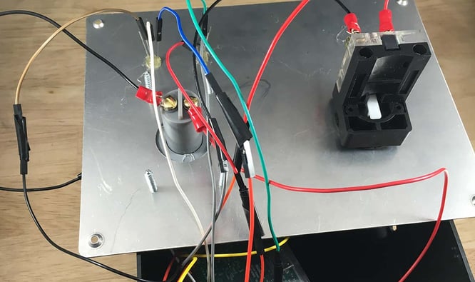
Ever wanted to experience the god-like power of launching a nuclear warhead without suffering the inconvenience of a war crimes tribunal? Well now you can!
 Haters gonna say it's fake
To mark the release of Losant's Python MQTT API client and REST API client, we will be constructing an Internet-connected two-man switch – think nuclear weapon launchers from the movies where two separate people have to turn a key – using a pair of Raspberry Pi 3 Model Bs. We'll send the key-turned state of each device to the Losant platform using our newly released Python SDKs and, if all keys are turned, allow an action to take place when a button is pushed on either device.
"Losant will neither confirm nor deny that is possesses nuclear arms or that it aspires to possess them."
Charlie Key CEO, Losant IoT
This being our official stance on the matter, Losant has instead rigged our launch-style switches to deploy our product documentation to the web. But once the button press reaches the Losant platform, we can take any number of actions.
Required Materials
- Two Raspberry Pi 3Model Bs with power supplies and microSD cards, along with keyboard and monitor connections for initial setup
- Four RGB LEDs (common anode or common cathode are OK)
- Two momentary electric key switches
- Two big ole red momentary pull-up resistor buttons
- Eight 22-18 gauge ring terminals (if you're using the key switches and buttons listed above)
- Eight resistors (types will depend on which LEDs you buy; in this tutorial we use four 1300 Ohm resistors for the red pins and four 560 Ohm resistors for the green pins)
- Breadboards, wire and female-to-female jumpers
Set Up Your Raspberry Pi 3
Before we can dive in, it will be necessary to get your Raspberry Pi 3 up and running with the base operating system. We recommend you follow the official Getting Started Guide and return here once you've formatted your microSD card, downloaded NOOBS and copied it to the card and installed the Raspbian operating system.
Also, be sure to set your Pi up to connect to your WiFi network. An Internet connection will be required in later steps.
Connect Switches, Buttons and LEDs
Now let's wire everything together, one Pi at a time. View the wiring diagram below for our schematic.
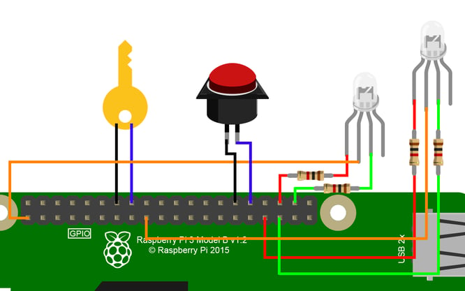
A few notes on this setup:
- Black lines represent ground connections. Red lines run to the red pins on the LEDs. Green lines are for green pins. Orange lines connect to 3.3V. And blue lines are for GPIO input.
- This schematic shows the setup for common anode RGB LEDs. If you have the common cathode variety, you will want to hook your common pins to the Pi's GND (ground) pins instead of the 3.3V pins as shown here.
- The diagram shows 1000 Ohm resistors connected to the common RGB LED pins. The type of resistors you will need will depend on the type of RGB LEDs you acquire.
- This shows the setup for the default pins included in the code repo. You can change these in the setup file if you desire.
Register the Devices in Losant
Assuming you already have a Losant account and have created an application, it's time to add each of our Raspberry Pis as devices in the platform. Things to note when creating each device:
- Name it anything you'd like (I called mine "RPi A" and "RPi B")
- Leave "Virtual Device" unchecked
- Give it a tag with the key "type" and the value "twoManSwitch"
- Give it two attributes: "isButtonPressed" (Boolean) and "isKeyTurned (Number)
- You will need to do this a second time for your other Pi.
Now we need to generate separate access keys for each device. While we could allow each device to use the same access key and secret, doing so would eliminate the benefit of a two-man switch as now either of the switch users could trigger the action without the other. So make sure to select "Restrict to Specific Devices" and then choose one of your Raspberry Pis at a time when generating each separate set of credentials. After each set is created, make sure to copy your device ID, access key and access secret to a safe place as we will need them later.
Set Up the Losant Workflow
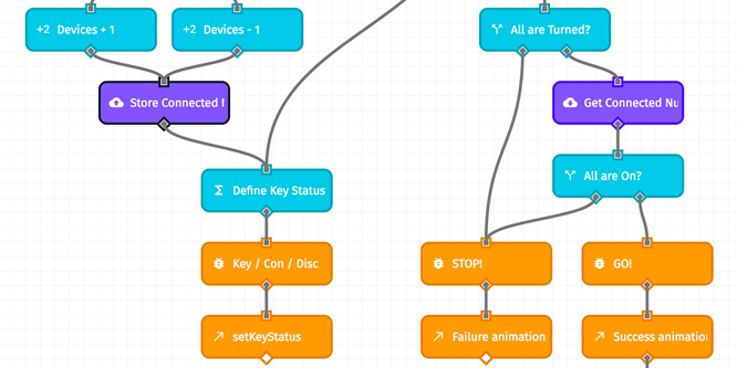
Now, let's set up our workflow to listen for key turns and button presses, and send commands back down to our Raspberry Pis.
- Create a new workflow in your application and import this workflow into it.
- In your "Get all Switches" node and all your trigger command nodes, make sure the "Device IDs / Tags" are configured to read the tag "type=twoManSwitch" – and that the tag was added to each of your devices when you registered them in Losant.
- To get you up and running quicker, this workflow simply sends a text message to a number of your choosing and posts an explosion animation to a Slack webhook on a successful button push. Go into the workflow's Globals tab and enter a phone number for where the message should be sent as well as a slackUrl. (If you want to skip the Slack portion, simply delete that node.) Or, you can set up your own series of nodes where the SMS node currently resides.
- Finally, make sure to click the "Deploy Workflow" button in the top right corner to activate it.
Add the Script and SDKs to the Pi
Finally, let's set up each of our Raspberry Pis with the two-man switch code.
- Open a terminal on your Pi, or connect to it via SSH, and clone the repo by running
git clone https://github.com/Losant/example-iot-two-man-switch.git - Next, let's set up our config file. Copy the example config file to a new file called "losantconfig.py". Navigate to the directory where you just cloned the iot-two-man-switch repository and, in your terminal window, run
cp losantconfigexample.py losantconfig.py. Then, open the new file in a text editor by runningnano losantconfig.py. - Where indicated to do so, make sure to enter the device ID, application key and application secret of your first Raspberry Pi, and the device ID of your other Pi. Also, if you happen to be using common cathode RGB LEDs, make sure to switch the LED_COMMON_MODE variable to "cathode". Unless you wired your Pi differently from the schematic above, the rest of the config file can be left as the defaults. Save your changes by pressing
Ctrl-O, thenReturn, and then exit the file by pressingCtrl-X. - Now we need to install the two Losant Python SDKs. In your terminal window, run
pip install -r requirements.txt - Optionally, if you'd like the script to run automatically when the Pi starts, you can follow these instructions. We adjusted the cron script to start one minute after boot to ensure we had an Internet connection.
- Now, follow these instructions a second time to set up your other Raspberry Pi.
Let's Run It!
Since we are accessing the Pi 3's GPIO pins, we'll need to run our script as the root user on each device. From the project directory, run sudo python twomanswitch.py. You should then see your LEDs light up red.
There are additional comments in the Python file as well as the Losant workflow to indicate how the switches work, but here is a quick overview:
- The key is turned on a device, and its state is reported to Losant as now being "engaged".
- Losant then sends a command down to both devices to turn one LED assigned to that device green to indicate that the switch is engaged.
- Disengaging the switch will then send a "disengaged" state to Losant, and the LED will turn red again.
- The button on either device can be pressed at any time; if either of the switches is disengaged (an LED is red), the button press will fail and the LEDs will flash red to indicate this (following the
Falsepath of the workflow's "All are Turned?" node). - If both keys are turned when the button is pressed, the press will succeed and follow the
Truepath of the "All are Turned?" node - If, after the script is launched, a device should go offline, that device's LED will turn off to indicate device's unreachable state, and the button press on the still-connected device will fail to succeed.
Next Steps

At Losant, we have the switches rigged up to deploy our product documentation on a successful button press. To achieve this ...
- On a successful press, we send a command to a third Raspberry Pi 3 Model B. That Pi has a short Node.js script running continuously, listening for commands using our JavaScript MQTT client.
- When a deployment command is received, the Node script runs
git pullandnpm installfrom its local documentation directory to get the latest code. - We then run two npm scripts to build our documentation using MkDocs and then to send the build up to Amazon S3, where it is hosted.
Now that you can use a Raspberry Pi 3 and our new Python API clients to send data to the Losant platform, you can modify the sample workflow to do a number of different things when the two-man switch is triggered. Run an AWS Lambda function, send a command to another device, tweet maniacal LOL's as your newfound sense of power splinters your connection with humanity ... It's up to you from here.