
The ESP32 is one of the most cost-effective modules available for both proof-of-concept and production use cases. With built-in WiFi and a healthy complement of GPIO, the ESP32 is a great fit as the primary module for a wide variety of IoT products.
Firmware development is one of the biggest challenges of working with any microcontroller, including the ESP32. On the spectrum of code difficulty, embedded firmware ranks near the top. That’s why for this tutorial we’ll be using the Losant Embedded Edge Agent (EEA). The EEA brings Losant’s low-code Visual Workflow Engine to resource-constrained devices and gateways, including the ESP32.
This tutorial provides step-by-step instructions for remotely monitoring and controlling an ESP32’s GPIO using the Losant Embedded Edge Agent’s drag-and-drop development environment.
Everything required for this tutorial is provided as part of the ESP32 and Embedded Edge Agent Losant application template. Everything shown in this tutorial can be done for free using Losant’s Developer Sandbox. Sign up for a free account to get started.
Before we dive in, let’s first take a look at the remote controlled GPIO in action.
ESP32 Module with External PSRAM
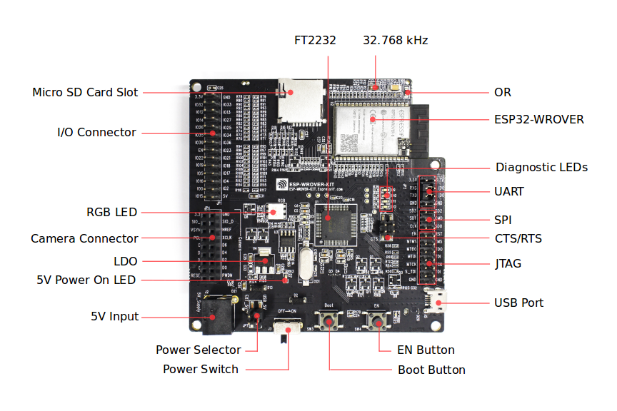
The Losant EEA requires approximately 1-2 MB of memory. This means not every ESP32 module is supported. For this tutorial, we recommend the ESP32-WROVER-E, which comes with 8 MB of additional PSRAM. If you’re new to the ESP32, we recommend the ESP32-WROVER-KIT, which can be purchased from Adafruit.
Install the ESP-IDF
The Espressif IoT Development Framework, or ESP-IDF, is the official software development environment for the ESP32. These tools are used to flash the ESP32 with the firmware that includes the Losant EEA.
To install and configure the ESP-IDF, follow their installation instructions.
Clone and Compile the ESP32 Firmware
For this tutorial, we’ve provided all required firmware, which can be found here:
https://github.com/Losant/eea-examples/tree/main/esp32
Clone the above repository to a folder on your computer.
Next, clone the Wasm3 repository into the esp32 folder. The purpose of this library is explained later in this tutorial.
cd path/to/eea-examples/esp32
git clone https://github.com/wasm3/wasm3.git
Before the firmware can be compiled, you’ll need to use menuconfig to set some configuration parameters.
cd path/to/eea-examples/esp32/
idf.py menuconfig
Once launched, you’ll see the following screen:
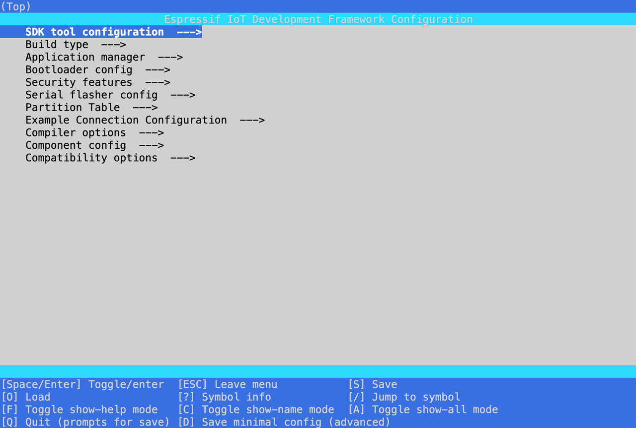 First, configure your WiFi details using the following settings:
- Example Connection Configuration -> connect using WiFi interface (enable)
- Example Connection Configuration -> WiFi SSID (set to your WiFi SSID)
- Example Connection Configuration -> WiFi Password (set to your WiFi password)
Next, configure the following settings so that the firmware will fit in the ESP32 module’s IRAM:
- Compiler options -> Optimization Level -> Optimized for size (-Os) (enable)
- Component Config -> FreeRTOS -> Place FreeRTOS functions into Flash (enable)
- Component Config -> Wi-Fi -> WiFi IRAM speed optimization (disable)
- Component Config -> Wi-Fi -> WiFi RX IRAM speed optimization (disable)
- Component Config -> mbedTLS -> Memory allocation strategy -> External SPIRAM (enable)
Lastly, this firmware uses non-volatile storage (NVS) to persist Embedded Workflow bundles between restarts of the ESP32. The default NVS partition is not large enough to hold a bundle, so this firmware includes a partition table that creates a new eea partition specifically for this purpose. To use this new partition table, configure the following settings:
- Partition Table -> Custom partition table CSV (enable)
- Partition Table -> Custom partition CSV file (partitions.csv, this will be the default)
You can now compile the ESP32 firmware. Do not flash the firmware yet, since there’s still one more change we need to make, which is done later in this tutorial.
idf.py build
About this Firmware
The EEA deploys Embedded Workflows to devices by compiling them to WebAssembly and publishing them over MQTT. Therefore, the majority of this code implements the Wasm3 runtime and the ESP-IDF MQTT client. This code applies to nearly any use case involving the EEA and the ESP32.
The implementation-specific code, which in this case is to remotely control GPIO, can be found in eea_registered_functions.cpp. Registered Functions are a way to expose native functionality to your drag-and-drop workflows. For this application, they are directly wrapping the ESP-IDF’s underlying GPIO and ADC functions. This means we can now invoke those functions however we want in our workflows using the Registered Function Node.
If you want to expose additional GPIO or ADC functionality beyond what’s available in this firmware, you can add as many Registered Functions as needed.
Create the Losant Application
For this tutorial, we’ll be using the Losant Enterprise IoT Platform for remote monitoring and control. If you don’t already have a Losant account, you can sign up for a free developer sandbox.
Every Losant resource (devices, workflows, dashboards) required for this tutorial has been provided for you as part of the ESP32 and Embedded Edge Agent application template.
Select the template from the New Application screen:

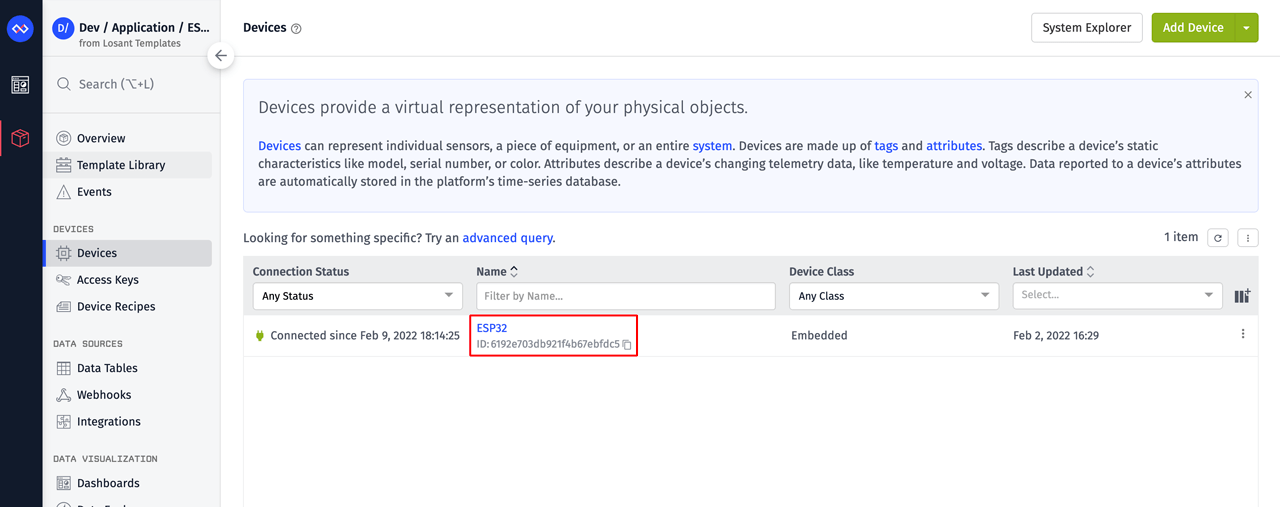
Once the application has been created, navigate to the device list. From here you’ll find a device already created to represent your ESP32. Click the device to open the device overview page.
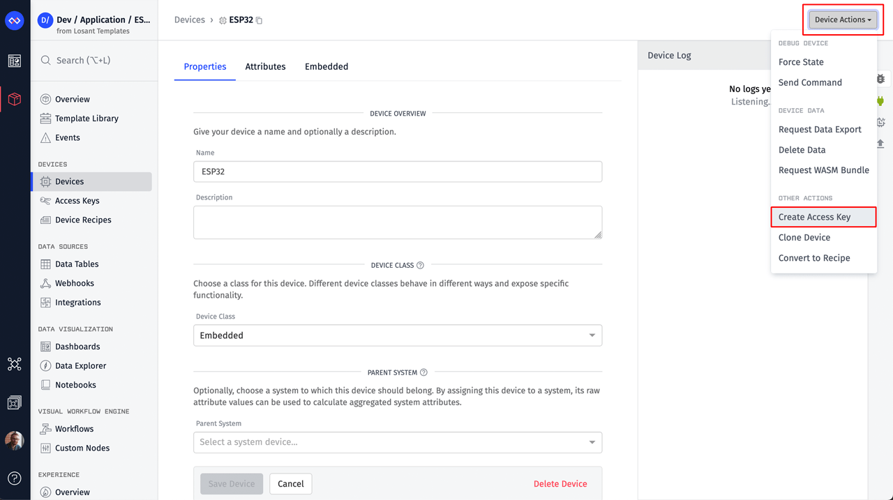
From the Device Actions menu, select Create Access Key. Access keys provide the authentication details that allow devices to connect to Losant’s MQTT broker. MQTT is how commands are sent to the device to remotely control the GPIO.
On the resulting popup you’ll see a newly generated access key and secret for this device. Copy/paste these somewhere safe. They’re required in the next step.
Lastly, copy the device ID. The device ID is available under the device’s Properties tab or by clicking the small copy icon next to the device’s name.
Flash the ESP32 Firmware
Now that you have authentication details for your device, you’ll need to edit eea_config.h. At the top of the file you’ll find three #defines. Change each to the value you copied in the previous step.
// Losant device credentials.
#define LOSANT_DEVICE_ID "REPLACE_WITH_YOUR_DEVICE_ID"
#define LOSANT_ACCESS_KEY "REPLACE_WITH_YOUR_ACCESS_KEY"
#define LOSANT_ACCESS_SECRET "REPLACE_WITH_YOUR_ACCESS_SECRET"
You can now build this firmware and flash it to your ESP32.
idf.py build
idf.py -p /dev/cu.xxxx flash
idf.py -p /dev/cu.xxxx monitor
The flash and monitor commands require the -p (port) parameter. This parameter tells the tool which port your device is plugged into. For details on finding this value, please read the ESP-IDF’s documentation on establishing serial connections.
The flash command writes the firmware to the device. The monitor command opens the IDF Monitor, which is extremely helpful during development and debugging. The monitor view can be exited using the control + ] keystroke.
This firmware contains verbose logging to help debug issues. If everything went well, you should see it create an MQTT connection, subscribe to the required topics, and publish the initial Hello Message to the platform. The device is now ready to receive and execute Embedded Workflows.
I (6036) EEA_MQTT: MQTT_EVENT_CONNECTED
I (6036) EEA_MQTT: sent subscribe successful, msg_id=5309
I (6046) EEA_MQTT: sent subscribe successful, msg_id=36592
I (6066) EEA_MQTT: Processing MQTT queue message.
I (6066) EEA_MQTT: Topic: losant/6192e703db921f4b67ebfdc5/fromAgent/hello
I (6066) EEA_MQTT: Payload: {"service": "embeddedWorkflowAgent","version": "1.0.0","bundle": "nullVersion","compilerOptions": {"exportMemory": true,"traceLevel": 2}}
I (6106) EEA_MQTT: MQTT_EVENT_SUBSCRIBED, msg_id=5309
I (6136) EEA_MQTT: MQTT_EVENT_SUBSCRIBED, msg_id=36592
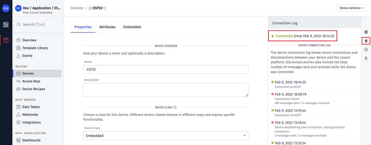
You can confirm the device is connected by opening the Connection Log on the device overview page in Losant.
Blink the ESP32 Onboard RGB LED
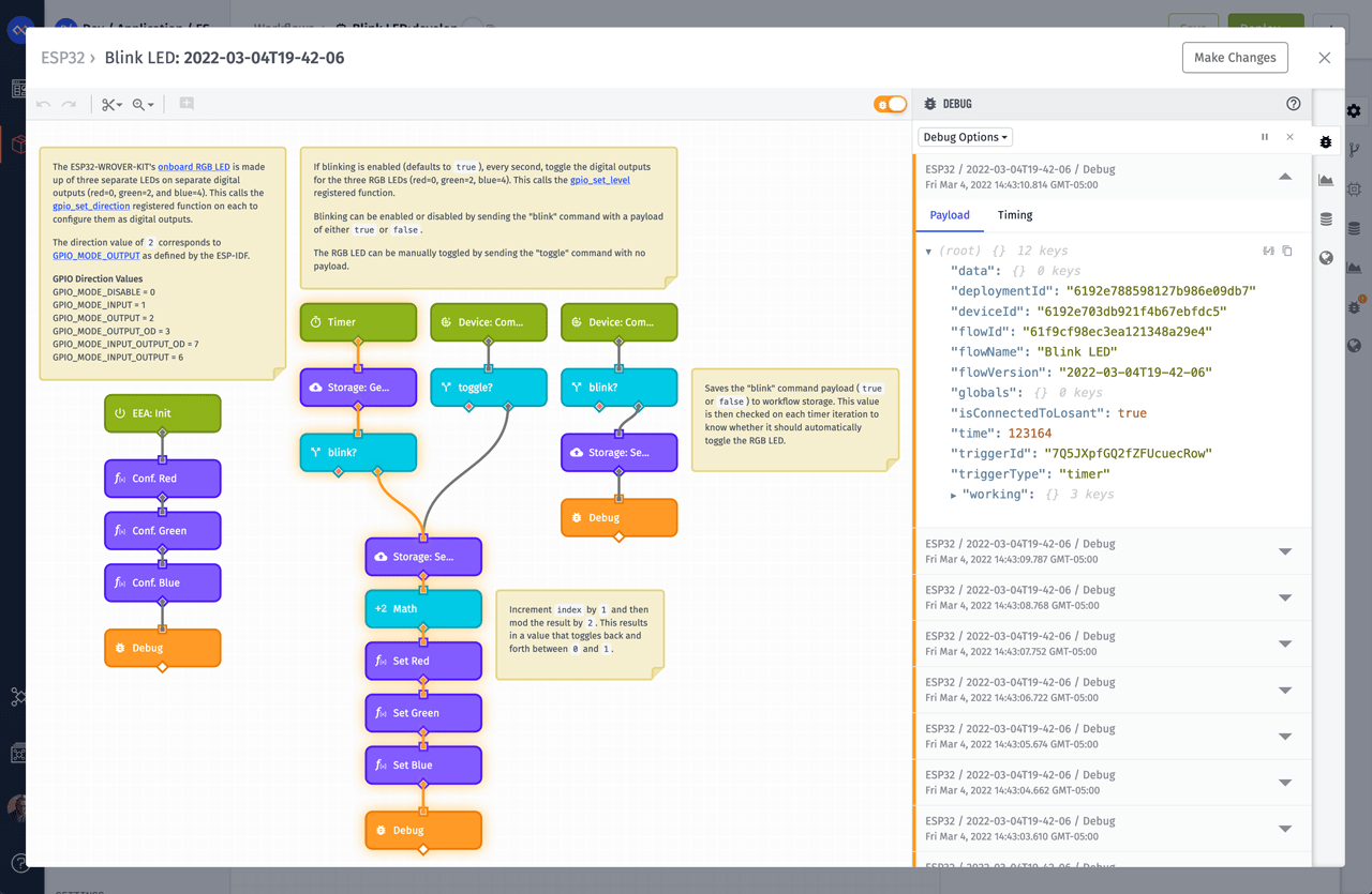
Inside your application, you’ll find an Embedded Workflow named Blink LED. Let’s open this workflow and see how it works.
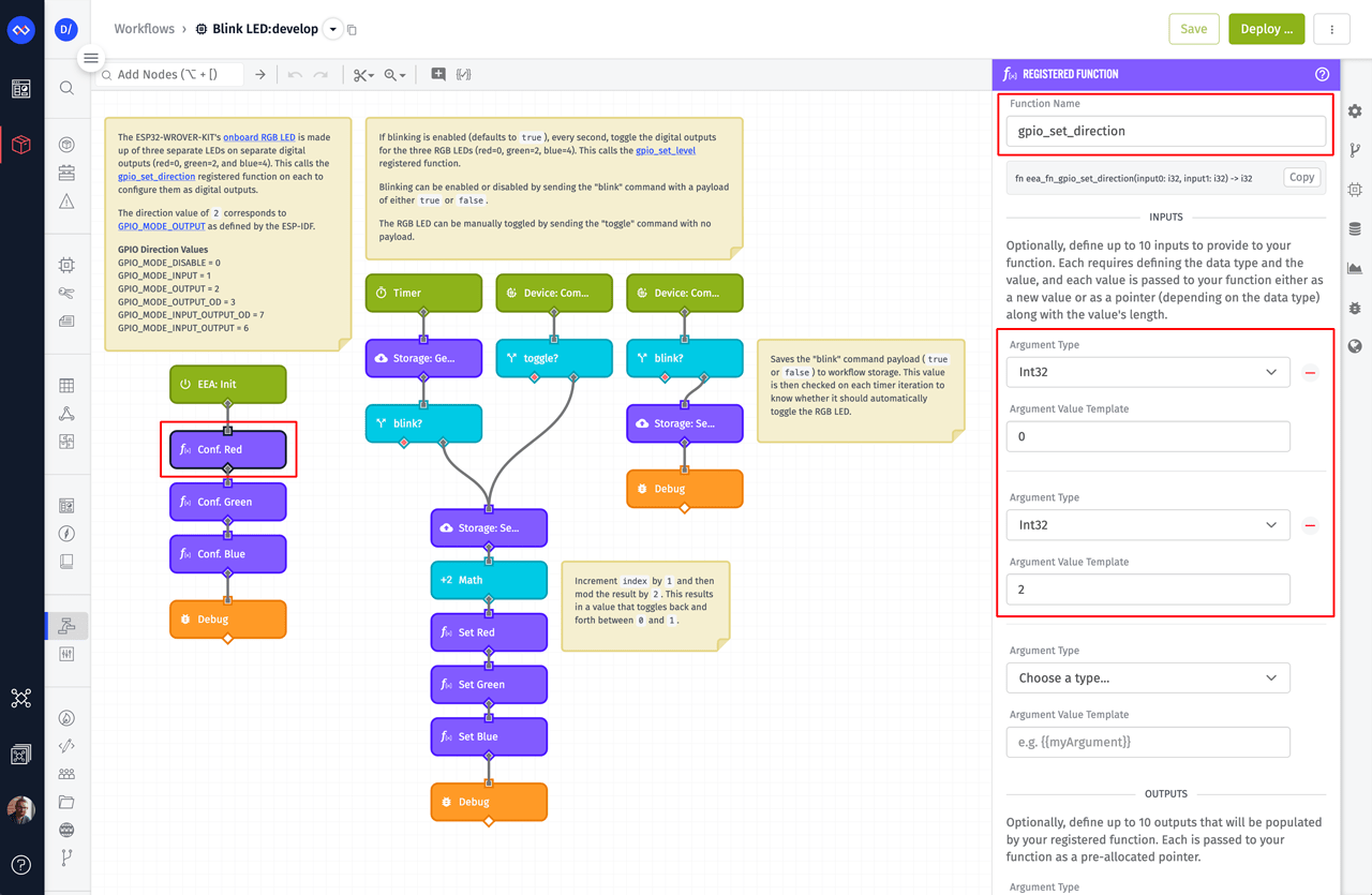
The image above is showing the configuration for one of the Registered Function Nodes that’s connected to the EEA: Init Trigger. The Registered Function Node is used to invoke functions that are defined in native code. In this case, we’re invoking gpio_set_direction, which directly wraps the gpio_set_direction function provided by the ESP-IDF.
Once this function is available, we can invoke it with any parameters we want, to configure any GPIO pin we want. In this case, the ESP32-WROVER-KIT RGB LEDs are connected to pins 0 (red), 2 (green), and 4 (blue). The node highlighted in the image above is invoked with the first input argument set to 0 (red) and the second input argument set to 2. The value of 2 corresponds to the gpio_mode_t value of GPIO_MODE_OUTPUT (i.e. digital output). The table below contains the numerical value of each GPIO mode. These values can be found in the ESP-IDF source code.
| GPIO Mode | Value |
| GPIO_MODE_DISABLE | 0 |
| GPIO_MODE_INPUT | 1 |
| GPIO_MODE_OUTPUT | 2 |
| GPIO_MODE_OUTPUT_OD | 3 |
| GPIO_MODE_INPUT_OUTPUT_OD | 7 |
| GPIO_MODE_INPUT_OUTPUT | 6 |
The other two nodes under this EEA: Init Trigger are doing the same for pins 2 (green) and 4 (blue). The end result is that all three LEDs in the RGB LED are configured as digital outputs.
Registered Functions are defined in the ESP32 firmware. The arguments and types configured in the node must match what’s defined in the firmware. For example, below is the code for the gpio_set_direction registered function. This code can be found in the file eea_registered_functions.cpp.
m3ApiRawFunction(eea_fn_gpio_set_level)
{
  ESP_LOGI(TAG, "eea_fn_gpio_set_level");
  m3ApiReturnType(int32_t)

  m3ApiGetArg(int32_t, pin);
  m3ApiGetArg(int32_t, level);

  int32_t result = gpio_set_level((gpio_num_t)pin, level);
  m3ApiReturn(result);
}
The two arguments are defined here:
m3ApiGetArg(int32_t, pin);
m3ApiGetArg(int32_t, level);
They are both Int32, which is what’s set as the argument type in the workflow node’s configuration.
Now that we have pins configured as digital outputs, we can set their values.
To the right of the EEA: Init Trigger, you’ll notice a group of nodes that control the state of the onboard RGB LED. The LED can either be blinked automatically using a Timer Trigger or be controlled manually using a Device Command. For now, let's focus on the Timer.
Connected to the Timer Trigger are a Storage: Get Value Node and a Conditional Node. These nodes check whether the LED should blink automatically. This behavior can be changed by setting the “blink” value in Workflow Storage to either true or false. We’ll cover changing this value using a command in the next section. By default, the value is true, and the LED will blink every 1 second.
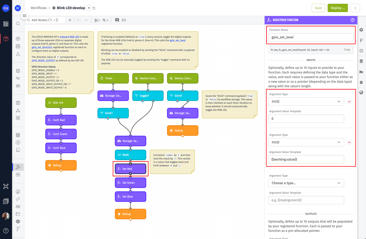
The following Storage: Set Value Node and Math Node are used to toggle a value back and forth between 0 and 1 on each timer iteration. The resulting 0 or 1 is then passed to the Registered Function Node that is highlighted in the image above. This registered function is invoking gpio_set_level, which again directly wraps the underlying gpio_set_level function from the ESP-IDF. This function sets the level of any digital output. This workflow is setting the level of the red (0), green (2), and blue (4) LEDs to either 1 (turn on) or 0 (turn off).
You can now deploy this workflow to your ESP32 using the Deploy button at the top right corner of the screen.
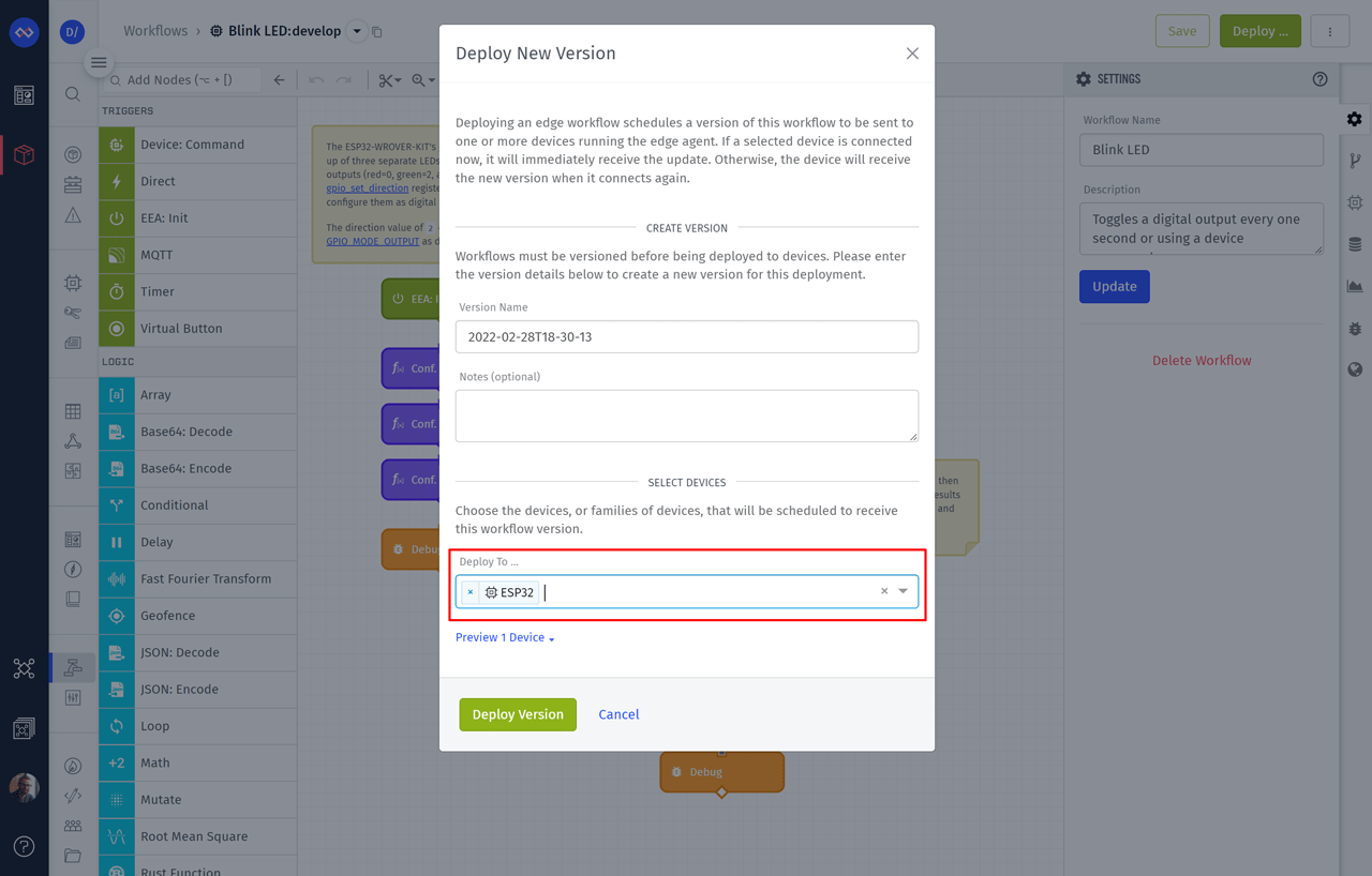
Deploying an Embedded Workflow takes approximately 30 seconds. Once the deploy is complete, you can click the Live Look icon to see the workflow’s debug messages in real time.
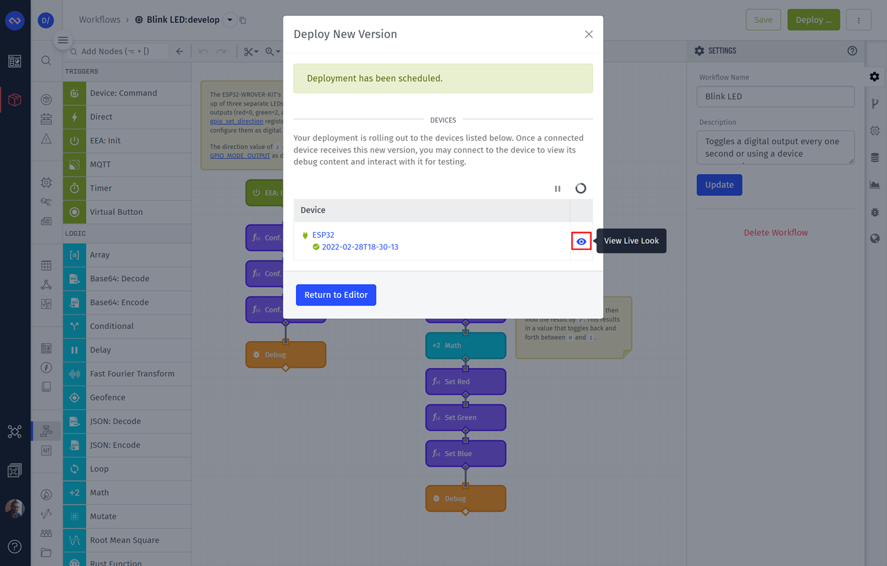
Now that the workflow is deployed and running, the result is a blinking LED.
Remotely Control the ESP32 Onboard RGB LED
To the right of the Timer Trigger, you’ll see two Device: Command Triggers. Beneath each trigger are Conditional Nodes that check for specific command names: either “toggle” or “blink”. The “toggle” command invokes the same nodes that we covered in the previous section. This command manually toggles the RGB LED on or off. The “blink” command enables or disables the automatic blinking by changing the “blink” value in workflow storage to either true or false.
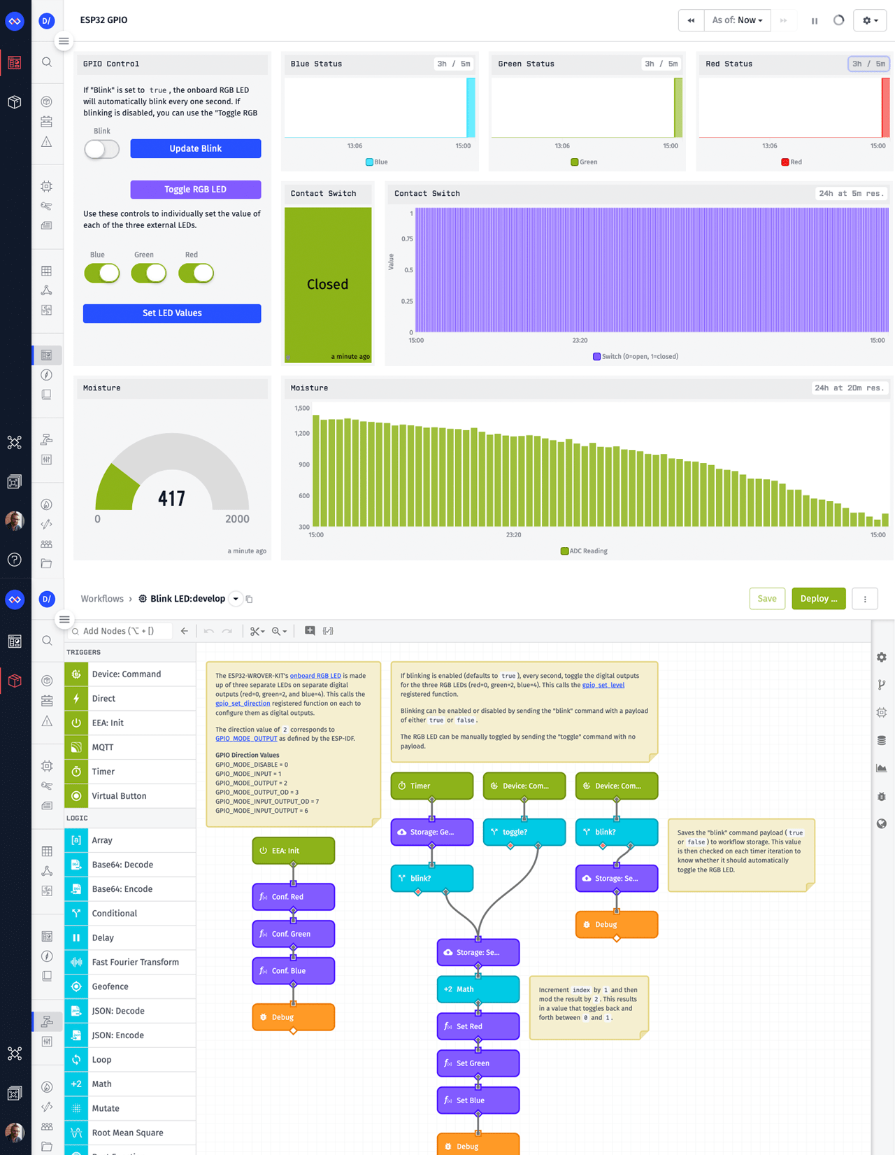
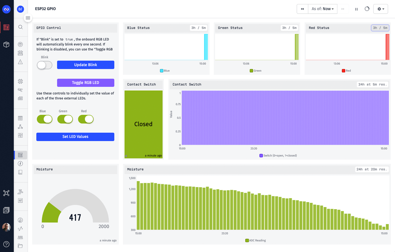
Sending commands can be done in a variety of ways, but for this tutorial, we’re going to send commands using a Losant Dashboard. In your application, you’ll find a dashboard named ESP32 GPIO. This dashboard contains an Input Controls Block that will send these commands to your device.
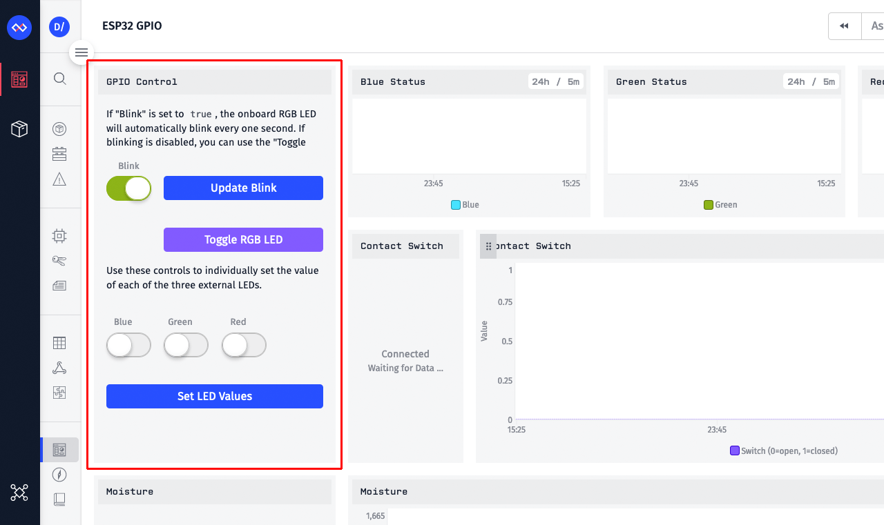
Most of this dashboard will be empty, but that’s because we haven’t started sending any GPIO data to the platform. For now, the only block we care about is the one highlighted above.
Input Control blocks are locked by default to help prevent accidental clicks. You can unlock it by clicking the settings icon in the top right corner of the block and clicking Unlock.
This block sends three different commands: “toggle”, “blink”, and “set-output”. The workflow you currently have deployed only understands the “toggle” and “blink” commands. We’ll cover the “set-output” command later in this tutorial.
Change the Blink toggle control to the off position and then click the Update Blink button. This will result in the “blink” command being sent to your device with a payload of false. You should almost immediately notice that your ESP32's LED stops automatically blinking.
You can now click the Toggle RGB LED button, which sends the “toggle” command, to manually turn the RGB LED on and off.
Connect Your ESP32 Inputs and Outputs
The inputs and outputs you connect are entirely up to you and what you want to control and visualize. For this tutorial, we’re demonstrating a variety of inputs and outputs to showcase the most common use cases:
- Digital Outputs
- Onboard RGB LEDs
- External red, green, and blue LEDs
- Voltage output for the moisture sensor
- Digital Input: magnetic contact switch
- Analog Input: moisture sensor
Below is a picture of the wiring diagram for this tutorial. The specific pins are explained below the image.
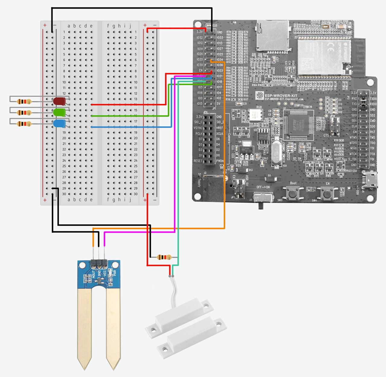
The external LEDs are connected to pins 23 (red), 18 (green), and 21 (blue). The onboard RGB LEDs, as we’ve seen previously in this tutorial, are connected to pins 0 (red), 2 (green), and 4 (blue).
The magnetic contact switch is connected to pin 19 and a pull-down resistor. It doesn’t matter which lead on the contact switch is connected to what (voltage or digital input). A contact switch works by connecting to the two together, which will cause the voltage from one lead to connect to the digital input on the other lead. The pull-down resistor causes the open state (i.e. contact switch is separated) to read as a low value (0). When the switch is connected, it becomes high (1).
And lastly, the moisture sensor’s signal output is connected to pin 34. We can then read this pin, as an analog input, to obtain the moisture level. The moisture sensor’s input voltage comes from pin 22. This allows us to turn on and off the moisture sensor only when it’s needed. Doing this greatly extends the life of the sensor. Connecting the sensor to a constant voltage source causes the leads to corrode quickly due to electrolysis.
It’s important to remember that not every pin is available for use. Refer to the GPIO documentation to ensure you’re not choosing a pin that’s being used by the board itself. Even though the ESP32 comes with two ADCs, only ADC1 can be used when also using WiFi.
Remotely Monitor ESP32 Digital and Analog Inputs
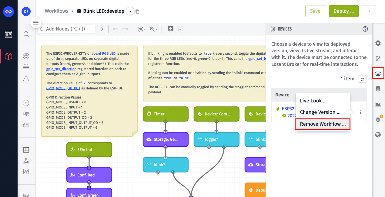
Before we continue, let’s remove the current workflow from your device. Losant supports deploying multiple Embedded Workflows to the same device, however the workflow we're about to deploy contains everything in the current workflow. So if we had both deployed, we'd be invoking duplicate operations when commands were received. Open the Blink LED workflow, select the Devices tab, and click Remove Workflow under the device menu.
Next, open the GPIO workflow. This workflow assumes everything is connected to the ESP32 as described in the Connect Your ESP32 Inputs and Outputs step. If you have different things connected to your ESP32, that’s not a problem. You can adjust this workflow based on your specific inputs and outputs.
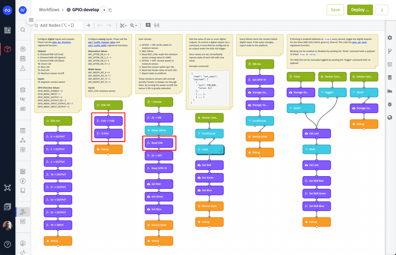
On the surface, it might look like there’s a lot going on, but many of the nodes in this workflow are things you’ve already seen, like configuring and controlling digital outputs.
The nodes highlighted above configure and read analog inputs from the ESP32’s ADC. Just like with the digital outputs, these invoke registered functions that directly wrap the following underlying ADC functions:
Using these registered functions, we can now create workflows that read any ADC channel we choose.
Surrounding the node named Read CH6 (the right-most highlighted node pictured above), you’ll notice two nodes that are controlling GPIO 22. We’re using pin 22 to send voltage to the moisture sensor only when it’s needed. This is a good example of the complex orchestrations between I/O that can quickly be built using workflows.
This workflow also introduces Device State, which represents a device’s time-series telemetry data. The Device State Node reports this data to the Losant platform for visualization, alerting, and ongoing application enablement.
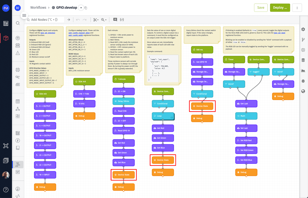
The image above has this workflow's three Device State Nodes highlighted. Each one reports state information under different scenarios.
Periodic Snapshots
The left-most Device State Node, under the 60-second Timer Trigger, reports a snapshot of all digital and analog values. This includes the moisture level (analog input), the contact switch value (digital input), and the value of each external LED (from workflow storage). The LED values are saved to workflow storage whenever a device command changes them.
To read the contact switch digital input, this workflow invokes a Registered Function Node that wraps the underlying gpio_get_level function.
Immediately Report State On Change
The other two Device State Nodes report state immediately when something changes. The middle one, under the Device: Command Trigger, reports the value of each external LED whenever the "set-output" command is received to change them. We'll take a closer look at this command later.
The right-most Device State Node, under the 500-millisecond Timer Trigger, reports state whenever the contact switch’s digital input changes. Since we want to know when the switch changes in near-real-time, the digital input is read on a fast interval (500 milliseconds). To detect a change, this workflow checks the newly read value against the previously read value that’s saved in workflow storage.
The combination of capturing periodic snapshots as well as immediately when something changes is a common implementation practice. The snapshots provide historical information for values that don’t change often and the immediate reports allow for real-time alerting and notifications using Application Workflows. This application template is using a 60-second snapshot interval for demonstration purposes, but in most production use cases, the interval would be much longer (e.g. 1 hour).
Let’s now take a closer look at the “set-output” command. This command is used to individually control the state of each external LED.
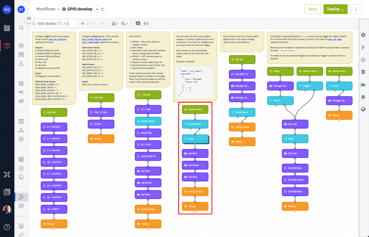
The “set-output” command includes a payload that defines the pins and their desired values. A Loop Node then iterates over every pin in the payload and sets the provided value. This concept allows you to control multiple GPIO values at once using a single command.
The Input Controls block on the ESP32 GPIO dashboard can be used to send the “set-output” command to individually control each LED.
Feel free to explore this workflow, see how it works, and make any changes that are required for your specific ESP32 GPIO configuration. When you’re ready, deploy this workflow to your ESP32 using the Deploy button.
Deploying this workflow demonstrates one of the primary benefits of the Losant Embedded Edge Agent. You were able to add entirely new functionality to your ESP32 without writing any additional firmware.
Remotely Monitor and Visualize Your ESP32 GPIO Data
When a device reports state, the state data is automatically saved to the device’s attributes. The ESP32 device created by this template already has attributes defined for the moisture sensor, contact switch, and each of the external LEDs. You can see these by opening the ESP32 device and clicking the Attributes tab.
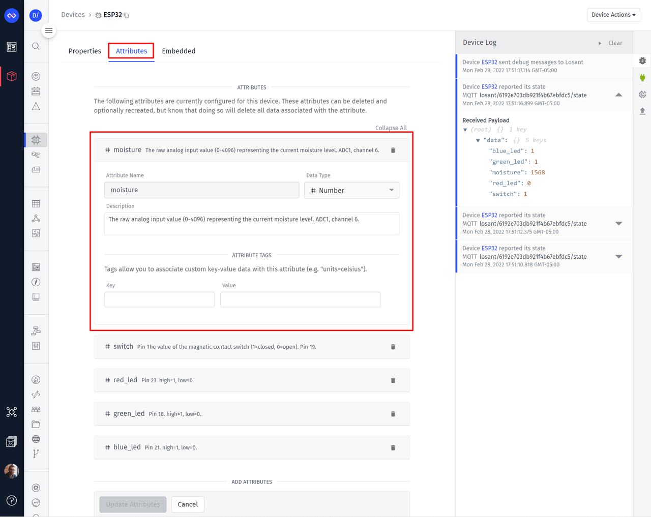
If your ESP32 is using different inputs and outputs, you’ll want to change these attributes to match. On the right side of the page you’ll also notice a real-time Device Communication Log. This log displays a message whenever the device reports state (among other things) and can be very helpful during early development and debugging.
Now that the ESP32 device is receiving state, data will begin appearing on the ESP32 GPIO dashboard.
Dashboards in Losant are drag-and-drop and are very approachable for new platform users. If you changed the device’s attributes, you will need to edit the blocks on this dashboard to use your specific device data. If you’d like a step-by-step guide for building dashboards, we recommend following the Losant Walkthrough.
Bring Your IoT Product to Life
The goal for this tutorial is to provide an overview of the Losant Embedded Edge Agent and how it can be used to quickly build IoT products using the ESP32.
Losant has a lot of functionality not covered in this tutorial, including End-User Experiences, which is where your fully branded and multi-tenant IoT applications come to life. Losant’s low-code IoT platform and the ESP32 make a powerful combination for a wide variety of IoT products and services.
If you’ve got comments, questions, or have used the ESP32 and EEA to build something amazing, please let us know on the Losant Forums. If you’d like to schedule a demo of the Losant platform or learn more about how the EEA can work for your organization, please contact us.