
One of the most successful ways for industrial equipment manufacturers to add value for their customers, and for their own organization, is to turn the equipment they manufacture into IoT connected products. This usually takes the form of remote monitoring, remote service, or condition-based maintenance applications. These applications increase the customer’s visibility into the equipment they operate, leading to reduced cost of ownership, improved customer satisfaction, and new revenue streams for the manufacturer.

In many cases, the data required to implement a remote monitoring application already exists within the equipment’s controller. From a technical standpoint, it’s a matter of tapping into that controller’s data and reporting it to an IoT platform like Losant.
Modbus is a widely supported communication standard that many controllers already support. One of the easiest ways to pursue the development of an industrial connected product is to retrofit equipment with an off-the-shelf gateway that can read Modbus and then report that data to the cloud.
The first challenge that manufacturers often face is the cost of adding a gateway to their equipment. Most general-purpose industrial gateways with cellular support cost between $500 and $1,000 USD. The Teltonika RUT240, which is the topic of this tutorial, provides a much more cost-effective solution. At the time of writing, a Teltonika RUT240 can be purchased for $199 from Mouser.
The Teltonika RUT240 provides an opinionated approach to Modbus that is less flexible when compared to an industrial gateway running something like Losant’s Gateway Edge Agent. That said, for many remote monitoring applications, the only requirement at the edge is to read and report the controller’s Modbus data. For those scenarios, the Teltonika RUT240 can be an excellent fit.
This two-part tutorial provides step-by-step instructions for configuring a Teltonika RUT240 to read Modbus data and report that data to the Losant Enterprise IoT Platform over MQTT.
Teltonika RUT240 Initial Setup
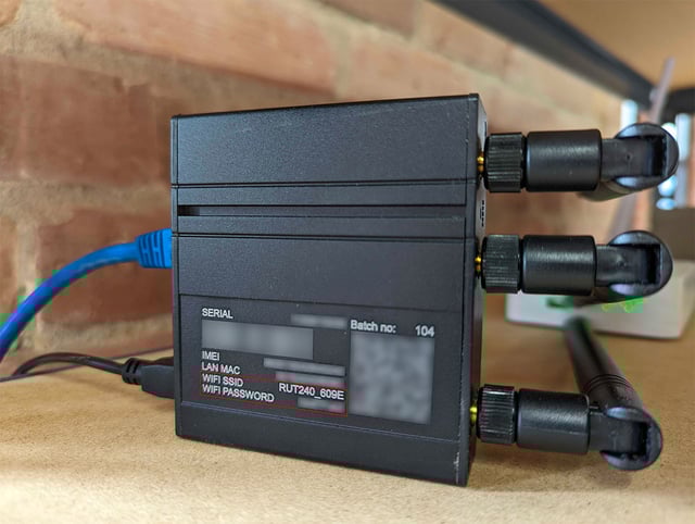
In terms of the RUT240 hardware, the setup only involves a few steps:
- Attach the three antennas (two are for cellular and one is for WiFi).
- Insert the SIM card for your cellular carrier. For this tutorial, I’m using a SIM from Hologram, a Losant partner.
- If applicable, plug an ethernet cable into the WAN port. This allows the RUT240 to communicate with the internet without using cellular data.
- Plug in the power adapter.
The RUT240 also has a LAN port, which can optionally be used to connect to the device’s network for initial configuration. For this tutorial, however, we’ll be connecting to the device’s auto-created WiFi access point.
Connect to the Teltokina RUT240’s WiFi Access Point
From the factory, the Teltonika RUT240 exposes a WiFi access point that can be used to access its internal network for configuration. The SSID and password for the RUT240’s access point are printed on the bottom of the device itself.
Once your computer is connected to the access point, you can access the RUT240’s web interface (WebUI) by navigating to http://192.168.1.1 with your browser.
The WebUI may not be available if a deactivated SIM card is plugged into the device. Ensure your SIM card is valid and activated. You can verify this by looking at the LED indicators on the side of the RUT240. The device is ready to go if the LEDs beneath the signal strength indicators are on and not blinking.
As of this writing, Teltonika RUT240 devices come from the factory with the legacy WebUI. This means your screenshots may look different than the ones below until the firmware is updated. Instructions for updating the firmware are in the next section.
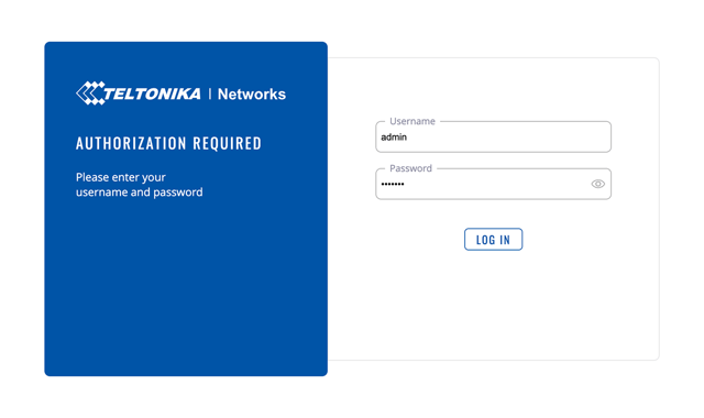
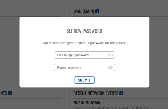
The RUT240 WebUI’s default username and password are admin and admin01. Enter these on the login page to enter the WebUI. You’ll immediately be prompted to change these credentials.
Update the Teltonika RUT240’s Firmware
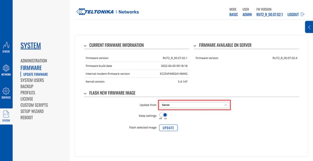
After connecting to the WebUI for the first time, you’ll want to immediately update the firmware. If your RUT240 is plugged into your network (WAN port), the easiest approach is to choose Update from Server. If your device is only on cellular, you may want to use the file option, which requires you to first download the firmware file from Teltonika’s website.
Since our device is also connected using ethernet, and therefore won’t be using cellular data for these updates, we’re choosing the server option.
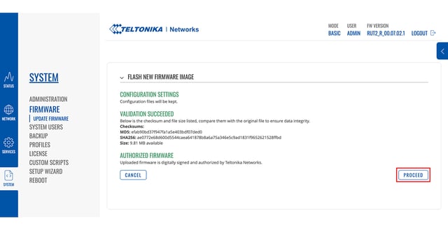
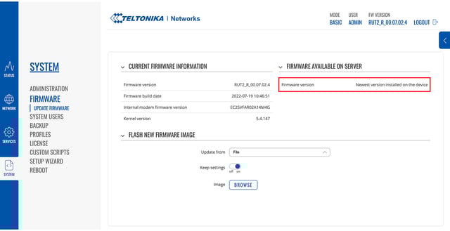
Updating the firmware usually takes 5 to 10 minutes, and you may need to update multiple times if multiple updates are available.
As part of the update process, the device will reboot, which will cause your computer to lose connection to the RUT240’s access point. Once the access point reappears, you can reconnect to the device and check for any additional updates. Once there are no more updates available you can continue this tutorial.
For this tutorial, we’re not changing any of the device’s default configuration. If there are specific configurations you need to apply to your device (e.g. firewall rules), this is a good time to set those.
Installing the Teltonika RUT240 Modbus Packages
The Teltonika RUT240 has several services that deliver many different use cases. For this tutorial we’re going to focus on the three services that give us the ability to read and transmit Modbus data to the Losant platform’s MQTT broker. These packages are:
- Modbus TCP Master: Provides the ability to request data from Modbus devices.
- Modbus TCP Slave: Allows parameters of the RUT240 device itself (e.g. System Uptime) to be read via Modbus requests.
- Data to Server: Periodically reports data being read by the Modbus TCP Master service to a cloud endpoint (e.g. MQTT).
The packages we’re installing only allow us to read and transmit Modbus data. They do not allow us to remotely write Modbus registers. The MQTT Gateway service provides a way to dynamically read and write Modbus registers over MQTT topics. This tutorial does not cover using this service, but depending on your use case, it might be worth investigating.
If you have experience with Modbus, Teltonika’s “master” and “slave” naming may be confusing since their functionality is reversed from the traditional Modbus master/slave definitions. A Modbus master is commonly a device exposing Modbus registers to be read and written. Teltonika’s Modbus TCP Master service is doing the opposite - it is acting as a Modbus slave, which is used to read data from one or more Modbus masters. This is something to keep in mind as the configuration will be confusing if you approach these services from the typical Modbus master/slave definitions.
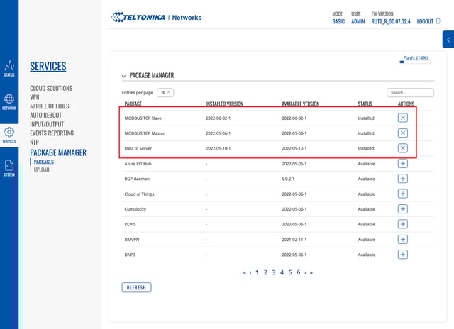
The RUT240 has a built-in package manager that can be used to install each service. Packages can also be downloaded from Teltonika’s website and uploaded to the device. The upload option works well if your device only has cellular connectivity, since it won’t consume bandwidth downloading the package. For this tutorial, we’ll be using the package manager:
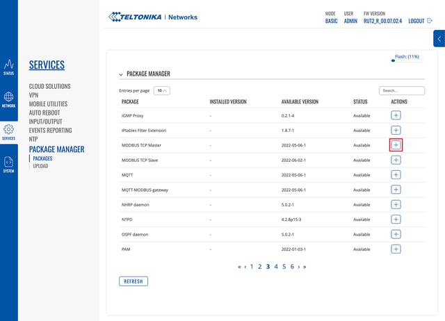
Click the install button (the “plus” icon) next to each of the three packages. Once installed, they’ll show up at the top of the package list with their status set to “Installed”.
You now need to switch the WebUI from “Basic” mode to “Advanced” mode. You can do this by clicking the “Basic” link in the header. Doing so will switch the WebUI and your new services will show up in the left navigation.
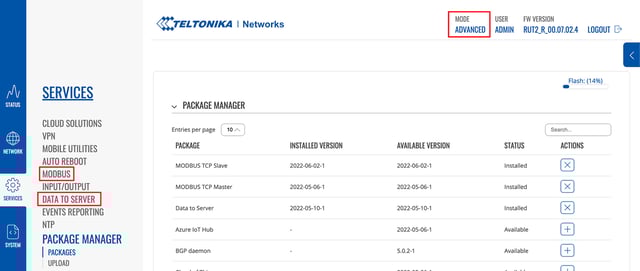
All required services are now successfully installed and ready to be configured.
Configure the Teltonika RUT240 Modbus TCP Slave Service
The Modbus TCP Slave service exposes the RUT240’s own parameters as Modbus registers. This allows us to read information from the device itself (e.g. system temperature) just like we would any other device on the network.
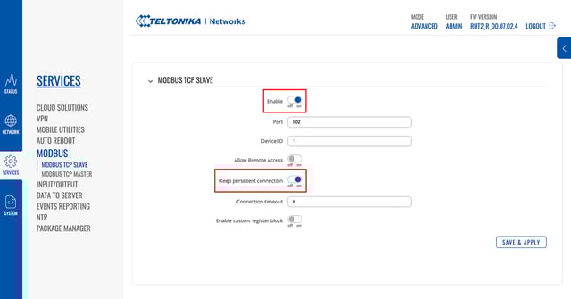
There’s very little configuration required for this service. At a minimum, you only need to enable it. We’re also going to enable Keep persistent connection to eliminate the overhead of connecting/disconnecting for each Modbus operation. We’re going to leave all other options configured to their defaults. Based on your specific use case, some of these other options may be helpful, so make sure to read the documentation to understand what’s available.
After clicking the Save & Apply button, we’ll be able to connect to this device using the Modbus TCP Master service to read and report a variety of device parameters.
Configure the Teltonika RUT240 Modbus TCP Master Service
The Modbus TCP Master service is what handles reading Modbus data from devices on your network. For this tutorial, we’re going to read data from two different devices. The first device will be the RUT240 itself, which we just enabled in the previous section. The second device will be an industrial controller that’s on the same network.
Reading the RUT240 System Parameters Using Modbus
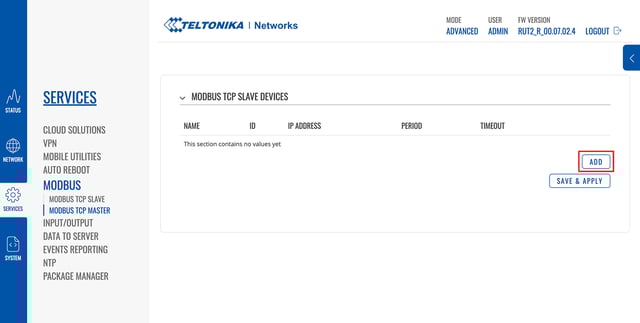
The Modbus TCP Slave service we installed in the previous section exposes a number of system parameters we can now read using the Modbus TCP Master service. When you first navigate to the configuration page for the Modbus TCP Master service, you’ll see an empty list of devices. Click the Add button to add a device to represent the RUT240.
First, provide the device configuration. The only two fields you’ll have to set are the Name and the IP Address. If you’re using the RUT240’s default configuration, the IP address is 192.168.1.1. You’ll also want to make sure the device is enabled by switching Enabled to the on position.
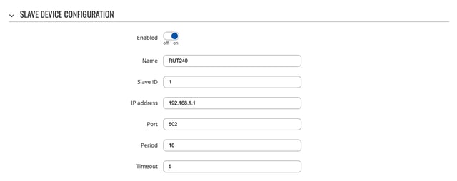
The Period option controls how often every Modbus register will be read. By default, it’s set to every 10 seconds. This rate is useful for testing, but in practice, reading the RUT240’s system parameters every 10 seconds is likely far more data than you’ll require. For production use cases, we recommend changing this to 3,600 seconds (1 hour).
The next step is to configure the requests, which represent the Modbus data to be read from the device. Each device may have many requests depending on how much data there is to read. To start, enter a name for the request and click the Add button. For the first request, we’re going to read the RUT240’s system temperature, so we named the request “system_temperature”.
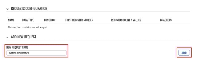
As soon as you click Add, an entry will show up in the Request Configuration table, where you can configure the details for this request.
The details for each request are specific to the device being read. For the RUT240, you can find the details for all available system parameters in the documentation for the Modbus TCP Slave service.
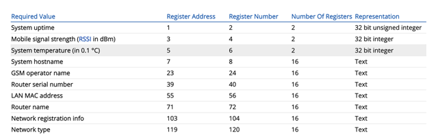
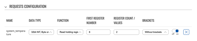
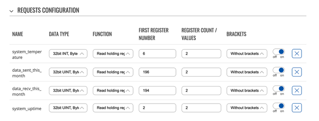
Looking at the system temperature row in the table above, we can see the following configuration values:
- Data Type: Set to “32bit INT, Byte order (1, 2, 3, 4)”. The dropdown for this configuration field includes two 32 bit options, each with a different byte order. Teltonika’s documentation doesn’t specify the byte order, but through testing we’ve determined the byte order to be little endian, specified as “(1, 2, 3, 4)” in the dropdown.
- Function: Set to “Read holding register”. Teltonika’s documentation doesn’t indicate the function, however when accessing Modbus data like this, it’s most commonly read from a holding register. Through testing, we’ve confirmed this to be correct.
- First Register Number: Set to “6” as specified in the table.
- Register Count / Values: Set to “2” as specified in the table.
- Brackets: Set to “Without brackets”. Brackets are useful if you’re reading multiple values and you’d like the result to look like an array (e.g. [13, 53, 32]) This is helpful when transmitting these values as a JSON string, since no additional encoding is required.
Before saving the configuration, or adding additional requests, this service exposes a very useful testing tool to ensure your configuration is correct.
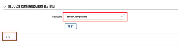
Choose the “system_temperature” request from the dropdown and click the Test button. This will perform a one-time read using your provided configuration. In this case, we received the value “370”. According to the Modbus register table above, we can see that the value is in increments of 0.1 degrees Celsius. So the actual value is 37 degrees C (98.6 degrees F). If the test appears to work correctly, you can save the configuration or continuing adding additional requests.
There are many system parameters available, but for this tutorial, we’re going to read system uptime, system temperature, mobile data sent, and mobile data received this month.
Feel free to browse the list of available registers and add as many as your application requires.
Reading Modbus Registers from Industrial Equipment Using the RUT240
There’s very little difference between reading Modbus from equipment on your network and reading Modbus data from the RUT240 itself.
The first step is to add another device to represent your equipment.
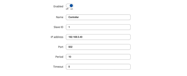
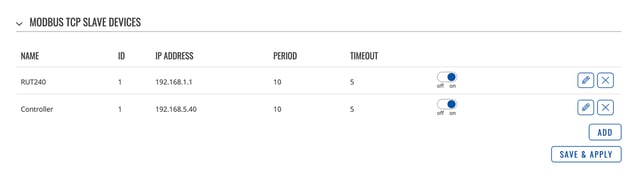
The actual configuration here depends greatly on your specific Modbus devices and network. For this tutorial, we’ve got an industrial controller on the network at 192.168.5.40. The RUT240 is plugged into this network via its WAN port.
The controller we’re using for this tutorial exposes two test registers that are constantly updated with random numbers.
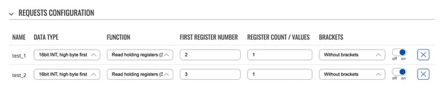
Modbus registers are specific to each type of device. Please refer to your device’s documentation for details. It’s important to note that “Register Number” on this configuration page is not the register address; it’s the address plus one. For example, the registers configured above are at addresses 1 and 2, however the register numbers must be configured to 2 and 3. This is because register addresses start with 0, but when referring to a register by number, you start with 1. In most cases, your device’s documentation will refer to registers by address, so just make sure to add 1 to avoid a considerable amount of confusion and debugging.
Once you’ve configured and tested all required requests and their Modbus registers, you can click Save & Apply to add this device. At this point, we’ve now got two Modbus devices configured. One is the RUT240 itself and the other is an industrial controller on our network.
This concludes part 1 of this tutorial. In part 2, we’ll cover how to publish, store, and visualize our Modbus data using the Losant Enterprise IoT Platform.