
Our goal here is to use the Losant office as a testing ground for our use cases around smart offices, smart buildings, and even smart campuses. This includes use cases like indoor position tracking, environmental monitoring, and meeting room availability indicators; which is the topic of this post. Not too long ago, we began creating the meeting room availability indicators and published a blog: Getting Started with the LIFX Remote API and Losant.
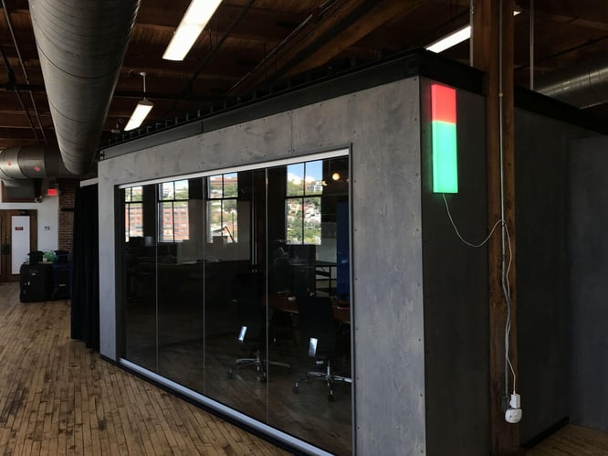
Today, we have the LIFX Tile lights on a wall to show if a meeting room is currently in use or not. If the room is occupied, the light representing that room turns red, and inversely, green. Keep in mind, in production use cases, our customers generally choose an enterprise lighting solution like Cree Lighting. In this case, we are using the LIFX Tiles as a proof-of-concept.
Here is what the first version looks like:
In the previous post, we reviewed how to use the HTTP API, but we learned that controlling the LIFX Tiles using the HTTP API only allows for basic functionality. Currently, the LIFX HTTP API treats the row of Tile lights like a single light and turns all the Tiles to the same color. The HTTP API was a great start, but to control the Tiles individually we are going to have to go deeper.
We are using three of the Tiles, and each Tile has an 8x8 grid of 64 LEDs, so we naturally want to be able to control the Tiles in a more fine-grained way. We can do this with the LIFX LAN Protocol.
LAN (local area network) is your local network. This means that instead of sending messages over the internet, we control the Tiles directly on the network using another computer. The LIFX LAN Protocol uses UDP (User Datagram Protocol), which means we will have to set up a gateway to send UDP messages to control the lights. We'll also need some way to send and receive signals from the gateway to the cloud.
All of this can be accomplished using the Losant Edge Agent. The Losant Edge Agent will run on the gateway (using Docker) to allow it to send and receive UDP message on the LAN. The agent also allows us to forward UDP messages to and from the cloud. The Losant Documentation covers, in detail, setting up the Edge Agent.
Ideally, you would want to have the Losant Edge Agent running on an always-on device like an enterprise IoT gateway computer. It’s recommended to have this set up to continue the article. It’s also possible to use Docker locally and run the edge agent on your personal computer while developing. This article also assumes that you have the LIFX Tiles configured and connected properly.
LE vs BE
When telling computers what to do at the bit level – think ones and zeros. We have to tell the computer which direction to read from. This uses the Little-Endian (LE) vs Big-Endian (BE).
From Wikipedia:
“A little-endian ordering places the least significant byte first and the most significant byte last, while a big-endian ordering does the opposite. For example, consider the unsigned hexadecimal number 0x1234, which requires at least two bytes to represent. In a little-endian ordering, the bytes would be arranged [ 0x34, 0x12 ], while in a big-endian ordering they would be [ 0x12, 0x34 ] "
Depending on your background, this concept may sound trivial or very complex, but it’s important to keep in mind when setting up the LIFX UDP message. Due to ordering, when crafting a message it’s sometimes easier to think in BE then convert to LE. According to the LAN protocol, the message sent from the gateway to the light will be LE.
Before we begin, we recommend that you review the LIFX docs and walk through creating a message that turns all lights green.
Finding Your LIFX Tiles IP Address
The first thing we must do is find the LIFX MAC address and IP address of the Tiles on our local network. You can do this in many ways. The easiest way is to log into your router admin portal and you should be able to find it there. Or, you can use other more advanced tools like Wireshark or Angry IP Scanner.
Once you have it, save it because you’ll need that later.
Setting Up the Message
Here is a sample message that LIFX shows you how to make:
31 00 00 34 00 00 00 00 00 00 00 00 00 00 00 00 00 00 00 00 00 00 00
00 00 00 00 00 00 00 00 00 66 00 00 00 00 55 55 FF FF FF FF AC 0D 00 04 00 00
This particular UDP message turns all lights green. The highlighted part is the target field. In this sample message, there is no target specified. This means this message goes out to all LIFX Tiles connected to your network. In the real world, we would want to specify which devices receive the message.
A MAC (Media Access Control) address is a unique ID number that allows us to identify every piece of hardware on the network. The MAC address should be in LE by convention, so there’s no need to convert it. In your own sample message, you would need to insert your MAC address into the first six bytes. Since the target is eight bytes, leave the last two bytes as zeros.
Making these messages by hand is a big pain, so let’s set up a sample workflow and get started. Make a new edge workflow with a Command Trigger > Function Node > UDP Send > Debug.
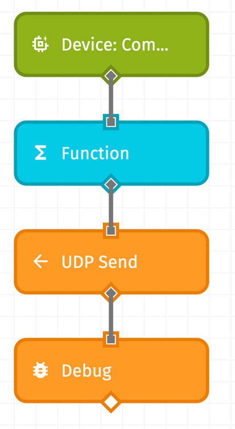
The bulk of the work is in the function node so let’s start breaking down the code.
On line 6, notice that we are hardcoding the size but if you want this to be dynamic, feel free to calculate the size and set this to the correct size later. A LIFX Tile UDP message is always the same size, so I’m just hardcoding this value.
If you are using a target MAC address, set fCombo to 0014 or use 0034 to send to all devices. The source (fSource) is sent in response to a message sent by a client, but we don’t get a response message so set this to all zeros. If you want to get messages back, set the source field and the res_required field (below).
We are using the Node.js Buffer library to set up our message; just remember to convert to little-endian. This code will set up a buffer that contains 29 04 as the first two bytes.
Next up is the frame address:
As mentioned previously, set your MAC address to the proper value. The rest of the frame address can be all zeros unless you want acknowledgment or response messages back.
Next, the Protocol Header:
The protocol header is the last part of the header, and the only interesting thing here is the pHeadType (line 10) which sets the message type. The SetTileState64 message time is decimal 715 or 02CB in hex. If you want to send other types of messages, be sure to set the message type and calculate the message size at the end. With this, we have the header all set up and ready to go!
The Payload
Now, the payload is where things get interesting and we get to tell our Tiles what to do. We have to send a SetTileState64 message to control our Tiles individually.
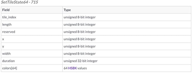
The tile_index is the index of the Tile you are trying to control. If you’re not sure which Tile is which don’t worry, it is pretty obvious when only one tile changes color.
The length is the number of Tiles you want to change, which means you can set to 1 to only change 1 Tile. This will be the number of Tiles from the tile_index set. So at index 0 if you set length to 2, then Tiles in index 0 and index 1 changes colors. LIFX has additional documentation on tile control if you would like additional detail.
LIFX lets us control 64 pixels in an 8x8 grid from a starting point specified by x and y so set these to zero and set the width to eight. Duration is the time in milliseconds for the tile to transition colors. Try playing around with this value for different effects.
Colors[64] is an array that represents the color and temperature for all 64 LEDs. HSBK is Hue, Saturation, Brightness, and Kelvin. Colorizer is a good tool to help HSBK color values. Kelvin is a scale of light brightness.
Hue is scaled from 0 – 360 degrees so use [degrees / 360 * 65535] to convert your hue. Notice, we are using writeUInt16LE to set up the buffers. I’m hardcoding the color here since we will always use the same colors, but you can make this more robust if you’d like.
The last thing to do is to make an array of all 64 HSBK values and convert that into a buffer to set up the final message. The Node.js Buffer library has a helper called Buffer.concat to add all the buffers together but it takes an array of buffers.
Notice, we are building the final buffer and placing on the payload at payload.working.
Configuring the UDP Node
That was a lot but we are now done with the hard part … high five! The last thing is to do is set up the UDP Node:
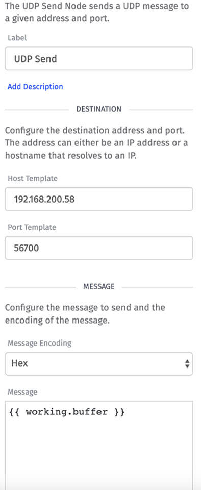
To do this, change your host template to the IP address of the LIFX light, leave the port as 56700 (that’s the default port for LIFX Tiles), and throw a big message into the message field.
To trigger this workflow on the edge, you would need to deploy it to a device running the Losant Edge Agent and trigger it using a device command.
At this point, you have successfully created a Losant Edge Workflow that sends UDP messages. There's a lot of additional functionality in Losant, including Experiences, that we eventually use to build our own smart office app.
If you've built something interesting, we'd love to hear about it. Please let us know in the Losant Forums.