
This article is a follow up from: Innovative Cloud PLC Communication Using Modbus TCP/IP and Losant.
In the article above, we introduced a high-level example of how Modbus TCP integrates with the Losant Enterprise IoT Platform. Since most PLCs aren't publicly accessible to the cloud, we introduced an edge gateway device to facilitate the integration. We will now take a technical dive into the integration and build an example application to demonstrate how the two systems talk to one another.
Let’s start with the following diagram:
.png)
In the diagram above, the PLC bidirectionally communicates Modbus over TCP to the gateway. The gateway bidirectionally connects to Losant using MQTT. The gateway device is the intermediary between the PLC, which is connected to all of the sensors we care about, and Losant. We must write an application that lives on the gateway that knows how to connect to the PLC and Losant. This application needs to be created because its logic is responsible for facilitating the communication between the PLC to Losant.
There are many types of gateways, all which have their set of specifications, but any gateway that can make an outbound connection via HTTP or MQTT can connect to the Losant platform.
This blog post will assume you have a Linux-based gateway that supports Node.js. Specifically, the Galil PLC that contains 16 coils and discrete inputs.
Create a Device in Losant
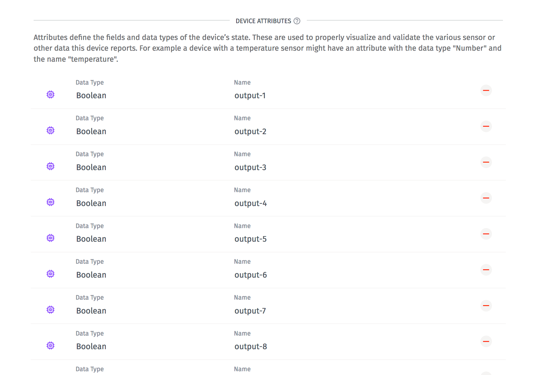
Before we create the application that runs on the gateway, we need to create a device in Losant that represents our PLC. To track the PLC information in Losant, create a device with attributes that represent each of the coils and discrete inputs on the PLC. For more understanding of coils and discrete inputs, please refer to our earlier post.
For my example, each coil is represented as "output-NUM" ,where “NUM” is the coil number. The same is true for discrete inputs but represented as input-NUM.
Once done, save the Device ID and generate a Security Key/Secret for the new Losant device.
Programming the Gateway
Now, we are going to program the gateway. In this section, you’ll need to be connected and have terminal access to your gateway. For this example, we are going to use Node.js, but Losant also provides Python and Ruby libraries. The example code is available for you on GitHub:
git clone git@github.com:Losant/example-modbus.git
After you clone, run:
npm installBefore we run, we have to update a couple of variables in the code. All of the magic is happening in index.js.
Let’s also walk through the code to take a look at what’s going on:
First we need to update host and port to be the IP address and port of our PLC. Next, we are setting up a Losant device. You should have already obtained these credentials from Losant. Lastly, we are setting up the Modbus TCP client with the host and port you provided earlier.
Let’s break down the next bit of code:
Here we are just establishing a connection to the PLC via Modbus TCP and to Losant.
Now, let’s take a look at the first part of the Modbus TCP client connection handler.
Here, we are reading the discrete inputs 0-15 every second. The client.readDiscreteInputs will communicate via TCP to the PLC. Then, we can take the output and create a JSON object that looks like this:
After we build up this object, we can send that to Losant as state. When you send data to Losant, you are reporting state. We also save this data so you can react to it or visualize it.
Lastly, we want to be able to control the PLC from Losant. Losant has the capability to send device commands to connected devices. Behind the scenes, the clients are subscribing to a special MQTT topic. However, here we are listening for commands from Losant. If we see a command named “output”, the command will contain the coil and the new value for that coil, command.payload.coil and command.payload.value respectively. Then, we can write the new value for that coil.
Overall, here is what our example application is doing. It’s reading all of the discrete inputs from the PLC and reporting them to Losant every second. On the other hand, it’s listening for Losant to send a device command back to then control the coils on the PLC.
Final Steps
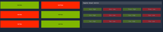
Lastly, we can create a dashboard to view various bits of information about the PLC. In the screenshot below, I have a dashboard that shows the status of six coils connected to Losant. On the other side, this dashboard has input controls to be able to control the status of the coil in real-time, which will reflect on the left side of the dashboard.
If you want to learn more about connecting Modbus to the cloud with Losant, feel free to contact us.