
In the manufacturing world there is a lot of valuable data that exists in the PLC. However, because it can be difficult to access, the information is rarely used to improve operations. When PLC data is moved to the cloud, it can be visualized to gain insights, make real-time business decisions, diagnose problem machines, and trigger alerts to critical team members.
We are able to solve this problem and bring the data that exists within the PLC to the next layer by using the Losant Enterprise IoT Platform along with the Losant OPC UA Browse, Read, and Write nodes. In this blog, we are going to walk through how to connect to an OPC UA server that exists on a Bosch Rexroth XM21 PLC and send that information to the Losant platform. By doing this, we will have the ability to read tag values from the PLC to Losant and also write values from Losant to the PLC tags.
Let’s walk through each component of the Losant platform that we will be using.
- Losant Gateway Edge Agent - The Losant Gateway Edge Agent is deployed on a customer device that has access to the local network to communicate with the OPC UA server.
- Losant Workflows - The two types of workflows that will be used are Edge and Application workflows.
- Losant Edge Gateway Workflow - Runs on customer gateway hardware and are executed by Losant’s Edge Agent. This workflow will communicate directly with the OPC UA server on the Bosch Rexroth PLC to read and write data.
- Losant OPC UA: Browse Node - This node browses an OPC UA server to see the data and tags that exist within the OPC UA server.
- Losant OPC UA: Read Node - This node can read a tag value in the OPC UA server.
- Losant OPC UA: Write Node - This node can write a value in the OPC UA server.
- Losant Application Workflow - Runs in the cloud and allows commands to be sent to the Losant Gateway Edge Workflow and then to the OPC UA server.
- Losant Dashboard - The Losant dashboard provides a flexible and powerful way to display your data from the OPC UA server and control your equipment.
WALKTHROUGH
In order to demonstrate how this works together, we are going to walk through a remote monitoring pump demo we’ve designed. All of the controls and feedback for this demo exist in Losant which reads data from the PLC via the OPC UA server and writes data to the PLC via the OPC UA server. Together, we’ll take two parts of this demo and walk through how to turn the pump output on from Losant and how to read the flow switch input data back to the Losant platform.
Getting Started with Losant
If you do not have a Losant account, you can sign up here. This gives you a free, fully functional developer license that will allow you to connect to your OPC UA server.
Create a new application or add to an existing application. Steps to create an application are here. The name I gave this application is ‘PLC Monitoring’.
Create an Edge Compute Device by following the instructions listed here. I named this ‘Edge Device’.
Install the Losant Gateway Edge Agent on a device that also has Ethernet access to the PLC and to the internet. Follow the instructions here for getting the Losant Gateway Edge Agent on a device. For testing purposes, you can use your personal laptop but it is not recommended for a long-term solution.
Create an Edge Workflow
This Edge Workflow will be deployed to a local device running the Losant Gateway Edge Agent and will be responsible for communicating with the OPC UA server using the OPC UA Browse, Read, and Write nodes.
Within the ‘PLC Monitoring’ application, we want to click on Workflows and then Add an Edge Workflow.
- Workflow Name: Bosch Rexroth PLC (any name here will work)
- Description: Remotely Monitor and Control Demo PLC (any description here will work)
- Minimum Agent Version: Edge Agent v1.7.0 (to use the OPC UA Browse, Read, and Write nodes, the Edge Agent must be at least v1.7.0)
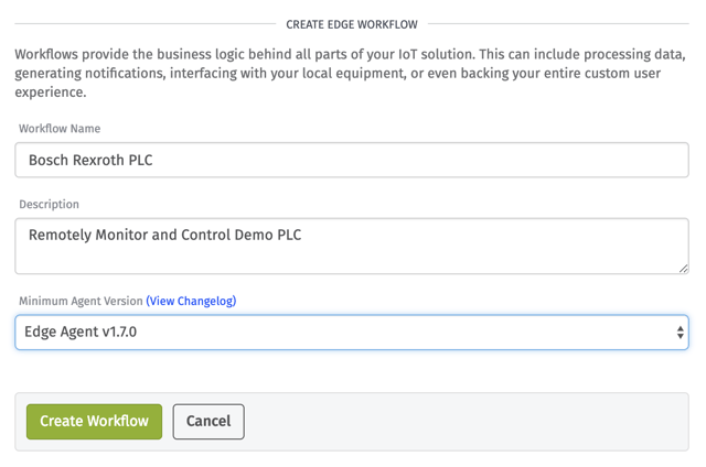
Click Create Workflow and your Edge Workflow will be created.
Now that we have our Edge Workflow created, let’s add three different flows to this one workflow. The first flow is to browse the data and tags that are in the OPC UA server. The second flow will be responsible for turning the pump on when a command from the Application Workflow is sent. The final flow is responsible for reading the flow switch every second to see if a flow is present. Go ahead and drag and drop each node and connect these nodes as shown below and then we will walk through each node.
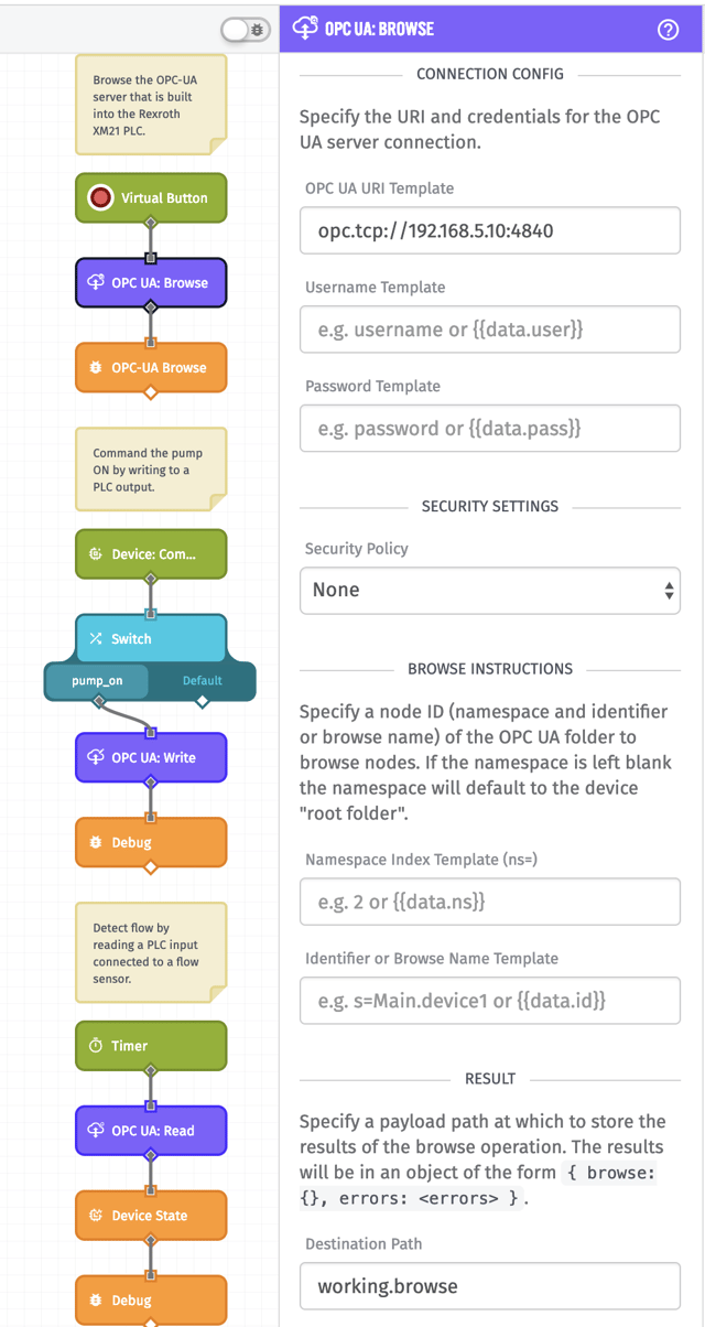
The Losant OPC UA: Browse Node will browse the tags and data in the OPC UA server of the URI provided. Fill out this node with the information shown in the screenshot above.
- Connection Config
- OPC UA URI Template (Required): opc.tcp://192.168.5.10:4840 (this is the address of the OPC UA server including the port number)
- Username Template (Optional): (if a login username is required then enter it here)
- Password: (if a login password is required then enter it here)
- Security Settings
- Security Policy: None (the OPC UA server that we are connecting to does not have security enabled, but if it did then this field allows different security policies to be used when communicating with the OPC UA server)
- Browse Instructions
- Namespace Index Template (ns=) (Optional): (a namespace can be given here and the node will browse all data and tags in that namespace - if this field is left blank, it will browse the root folder)
- Identifier or Browse Name Template (Optional): (an identifier or name that identifies the tag\folder to browse of the namespace index provided in the previous field)
- Result
- Destination Path (Required): working.browse (this is where the browse data will be returned on the payload)
An example output of the Losant OPC UA: Browse Node is shown below in the Debug window.
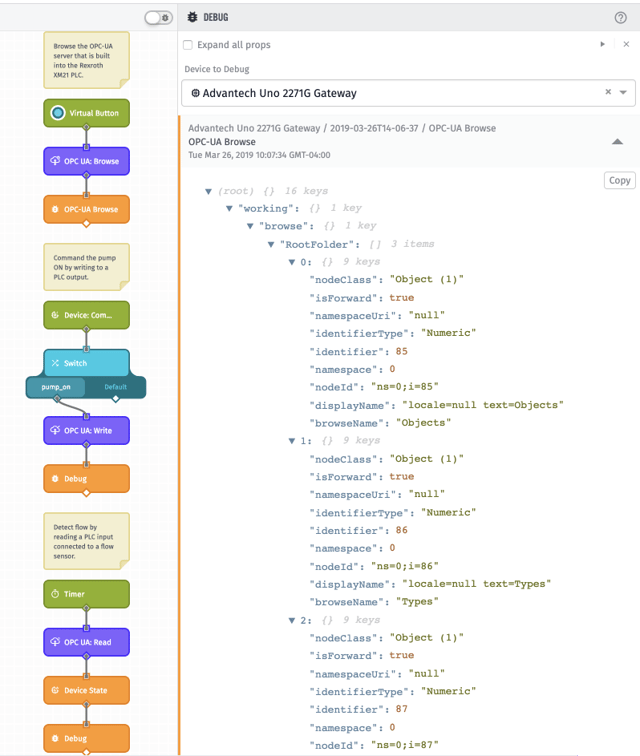
If we then wanted to browse the Objects folder that is shown in the screenshot above to see the data and tags in this folder, we could use the Losant OPC UA: Browse Node again and change the Browse Instructions as shown below:
- Browse Instructions
- Namespace Index Template (ns=) (Optional): 0
- Identifier or Browse Name Template (Optional): i=85
Let’s now move on to the next flow to show the Losant OPC UA: Write Node.
The Device: Command Trigger will trigger the second flow when a device command from the Application Workflow is made to our ‘Edge Device’. Do not worry about how this command is made from the Application Workflow yet, we will cover that below. There is no configuration needed for this Device: Command Trigger.
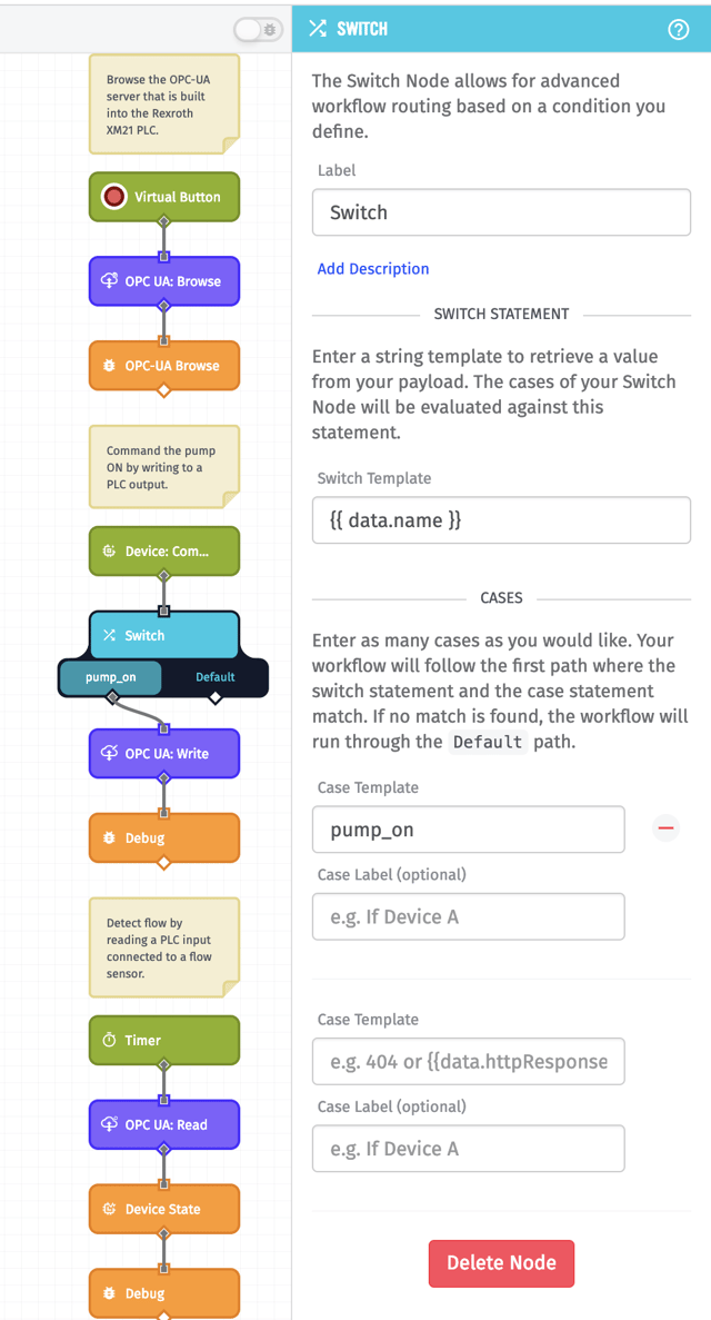
The Switch Node will allow us to choose different paths to take depending on the command the Application Workflow sends. For now, just fill in the fields as shown below and we will get more into this later.
Next is the Losant OPC UA: Write Node. This node will write all tag values configured within this node for the OPC UA server of the URI provided.
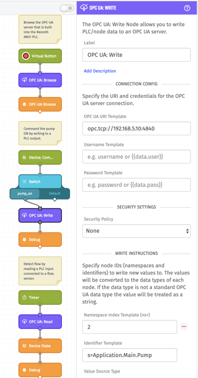
- Connection Config
- OPC UA URI Template (Required): opc.tcp://192.168.5.10:4840 (this is the address of the OPC UA server including the port number)
- Username Template (Optional): (if a login username is required then enter it here)
- Password: (if a login password is required then enter it here)
- Security Settings
- Security Policy: None (this allows different security policies to be used when communicating with the OPC UA server)
- Write Instructions
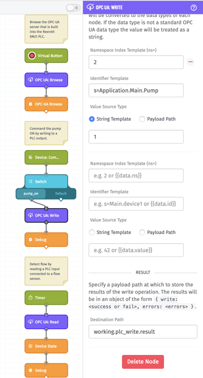
- Namespace Index Template (ns=) (Required): 2 (this is the namespace of where the tag we are writing to exists in the OPC UA server - if the namespace index is not known, then use the Losant OPC UA: Browse Node to find this tag to get this information)
- Identifier Template (Required): s=Application.Main.Pump (the ‘s’ signifies that I will be giving the identifier as a string and ‘Application.Main.Pump’ is the identifier of the tag I am writing to the OPC UA server - if the identifier is not known, use the Losant OPC UA: Browse Node to find this tag)
- Value Source Type (Required): String Template with a value of 1 (this signifies that I am entering a string. If Payload Path is selected then a value from my payload can be used. A value of 1 will be written to this identifier)
- Result
- Destination Path (Optional): working.plc_write.result (this provides feedback (either ‘success’ or ‘errors’ with the errors listed) from the write onto the payload)
In our PLC program, we have a tag named ‘Pump’ which drives the output to turn the pump on. We are writing a value of 1 to this tag. We are also configuring the optional Destination Path so that we get feedback of the OPC UA write on the payload.
This completes the Edge Workflow for writing to the PLC. Now let’s read a PLC tag which is connected to a flow sensor input. The Timer Node in this example is set to one second. Every second, it will trigger this workflow.
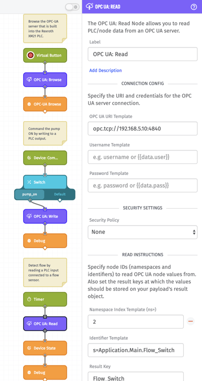
The Losant OPC UA: Read Node will read all tag values configured within this node for the PLC of the URI provided.
- Connection Config
- OPC UA URI Template (Required): opc.tcp://192.168.5.10:4840 (this is the address of the OPC UA server including the port number)
- Username Template (Optional): (if a login username is required then enter it here)
- Password: (if a login password is required then enter it here)
- Security Settings
- Security Policy: None (this allows different security policies to be used when communicating with the OPC UA server)
- Read Instructions
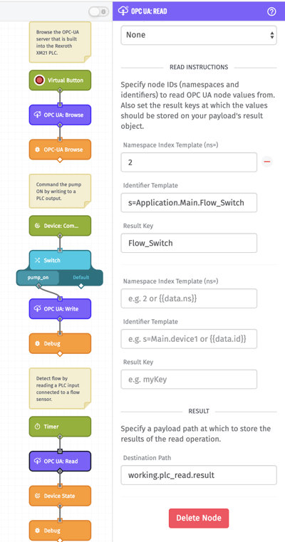
- Namespace Index Template (ns=) (Required): 2 (this is the namespace of where the tag we are reading from exists in the OPC UA server - if the namespace index is not known, then use the Losant OPC UA: Browse Node to find this tag to get this information)
- Identifier Template (Required): s=Application.Main.Flow_Switch (the ‘s’ signifies that we will be giving the identifier as a string and ‘Application.Main.Flow_Switch’ is the identifier of the tag I am reading from the OPC UA server - if the identifier is not known, use the Losant OPC UA: Browse Node to find this tag)
- Result Key (Required): Flow_Switch (any name here works - the result of the read will store the value of this read to this key on the Destination Path - we will set the Destination Path next)
- Result
- Destination Path (Optional): working.plc_read.result (this is the payload path that the Result Keys for each identifier will go to)
This node shows that we will be reading a tag named ‘Flow_Switch’ from the OPC UA server. The result of this read will be put on the payload as the Result Key, which in this case is also named ‘Flow_Switch’. The Result Key (‘Flow_Switch’) will be put onto the payload at the Destination Path that was configured (working.plc_read.result).
The next node updates the Device State. I created a device named Flow_Switch as Device Type Peripheral and I am updating a number attribute I created named ‘flow’ with the response from the previous OPC UA: Read Node.
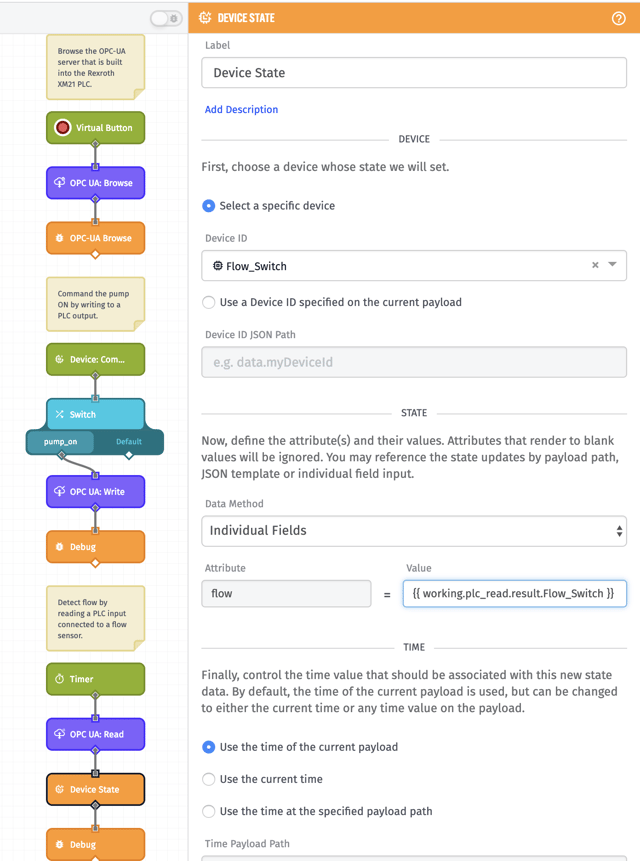
The Device State Node allows us to update the Flow_Switch device each time we trigger a read on this OPC UA tag. Configure the node so that the attribute ‘flow’ for the Flow_Switch reflects what is being read from the OPC UA server which is accessible from the payload at working.plc_read.result.Flow_Switch.
Deploy the Edge Workflow
To deploy the workflow, click Save in the top right corner and then click Deploy which will bring up a pop-up box like the one shown below.
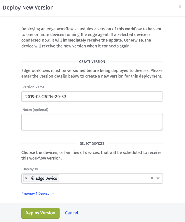
Any version name can be given but it must be unique each time you deploy so using a timestamp works well. Select the device(s) that this should be deployed to which in our case is the ‘Edge Device’ that we created earlier. Then we can click Deploy Version to have this workflow deployed to our Edge Agent.
Create an Application Workflow
This application workflow will command the pump from the cloud. Follow the same steps that we used to create an Edge Workflow but this time select Application Workflow instead of an Edge Workflow. Once this workflow is created, then create the flow as shown below.
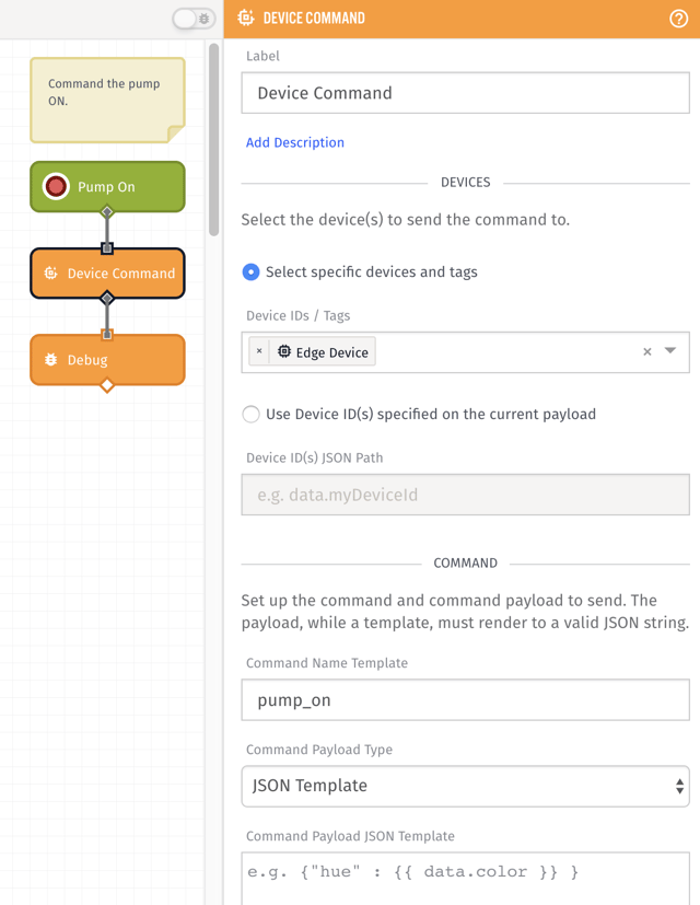
The virtual button named Pump On (this can be named anything) will trigger this workflow when this button is clicked - no configuration is needed for this node. The Device Command node will send a command named ‘pump_on’ to the ‘Edge Device’. This ‘pump_on’ command was used earlier to trigger the Edge Workflow and allow the Losant OPC UA: Write Node to execute. Once this workflow is created and configured, we can then press the Save and Deploy button at the top right corner. Now, if the Pump On virtual button is clicked, the command ‘pump_on’ will be sent to the edge agent on ‘Edge Device’ through the payload path ‘data.name’ and trigger the Edge Workflow that will write to the OPC UA server to turn the pump on.
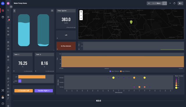
Dashboard
Now that we have all of this set up, a dashboard can be created to display the information we are reading from the PLC. The dashboard shown below is from our pump demo and built by using easy drag and drop visualization blocks. To find out more on how to build a dashboard, look here.
WHAT’S NEXT?
Now that you know how to use the new Losant OPC UA Browse, Read, and Write nodes, use them to connect to the machines on your factory floor. You can start by pulling machine state data and alarms and warnings for each of your machines. Using the Losant Dashboard, you can start tracking downtime on each machine to find your problem machines and also find which alarms are causing the most problems. If you have any questions, check out the Losant Forums. If you want to take your project further, we would love to learn more about your use case.