
Since launching the Losant platform, one of our users' most requested features has been the ability to control their devices directly from their dashboards. By bringing this functionality into the primary interface, we've made it so that most users never have to leave their dashboards for day-to-day use.
To commemorate the launch of the Input Controls Block feature, we'll set up a dashboard for a common use case: controlling the colors of an array of lights.
Demonstration Setup
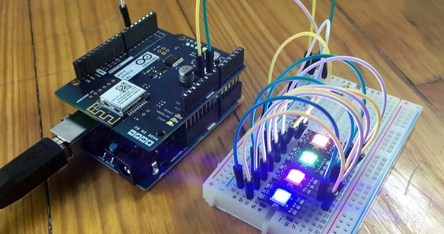
In a true home lighting setup, we would configure a gateway device in Losant (likely a Raspberry Pi) and set up each bulb (a Philips Hue or similar product) as a peripheral of that device. For our demonstration purposes, we are using an Arduino 101 with a WiFi shield as a standalone device and individual Adafruit NeoPixels to represent four different bulbs.

When setting up the Arduino 101 as a device in Losant, we're giving it attributes "led0Color", "led1Color", "led2Color" and "led3Color" and each should be of the type "String".
The Arduino has this sketch loaded onto it, which allows the device to listen for the "setColor" command and to report the state of each LED back to the platform.
Need help with a similar setup? Check out these guides for more info:
- Arduino 101 Getting Started Guide
- Adafruit's NeoPixel Überguide
- Installing Losant's Arduino SDK and Libraries
Configuring the Dashboard
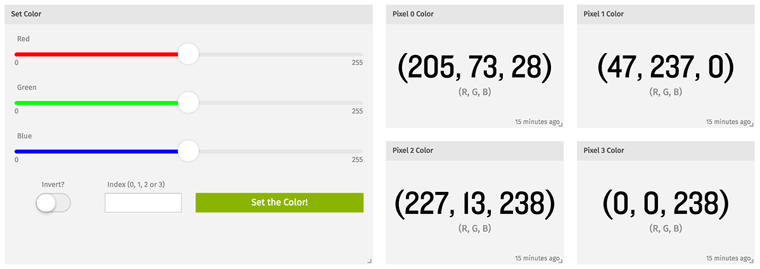
Create a new dashboard for managing our lights and viewing their current state, and then add a new Input Controls Block. We'll be adding six control components to the block:
- Three range inputs for our red, green and blue light values.
- Each input should have a minimum value of 0 and maximum value of 255.
- Each default value can be anything in between the min and max; I set it right at the middle at 127.
- Set each step at 1.
- Give each a label that makes sense (e.g. "Red", "Green", and "Blue").
- The three separate inputs should each have a unique Template ID. These can be anything you'd like, but I named mine "red", "green" and "blue" respectively.
- Optionally, each slider can be given a unique color. These can also be any value but I set each slider's color to match the values they control. For example, my red slider color is set at #ff0000 (pure red).
- One toggle input for inverting the color we've set.
- Label it "Invert?".
- Default Value should be "false".
- Set the Template ID to "invert".
- Color can be any value; I set mine to "#000000".
- One text input for optionally changing the color of one LED at a time.
- Set the label as "Index (0, 1, 2 or 3)". If one of these numbers is set, only that LED will change; otherwise, all LEDs will change.
- The Template ID should be "index".
- Leave the Default Value blank.
- One button input for sending all of our data to the microcontroller.
- Label and Color can be any values you'd like. Mine are "Set the Color!" and the default green, respectively.
- Leave On Click ... set to "Send Device Command".
- Set the Command Name to "setColor", which is the command name we're listening for on our microcontroller.
- Set the Payload to the following ...
{Each {{templateId}} in the payload will be run through Losant's Handlebars templating engine before the payload is sent with the device command, so the values of our individual controls will make it to the device.
"r":{{red}},
"g":{{green}},
"b":{{blue}},
"inverted":{{invert}},
"index":{{index}}{{^index}}999{{/index}}
}
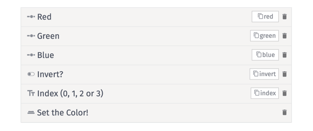
Once all of the input components are set up and configured, we can rearrange and resize the components as we see fit within the block. It's up to you how to arrange your sliders, toggle, text input and button.
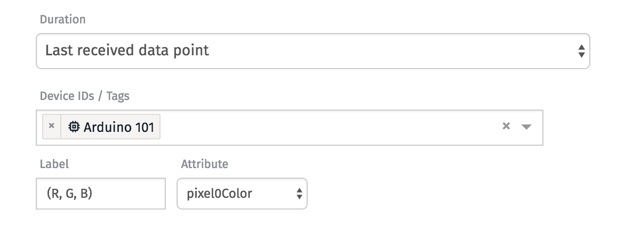
After we've saved our Input Control Block, let's create four individual Gauge Blocks for reflecting the state of each of our LEDs. Each block should reflect the state of one of our microcontroller's four color attributes (led0Color, led1Color, led2Color and led3Color).
Controlling the Lights
With our microcontroller loaded with the sketch and our Neopixels wired up, we're ready to change the colors of our LEDs from the dashboard. We can individually change the red, green and blue values before sending the color to the board, and we can also opt to change just one LED's color or change all of them with each press of the button. Then, the next time the dashboard data refreshes, we'll see what the RGB color of each LED is as of its last reported state.
Next Steps
Now that we can send commands to our devices straight from a dashboard – and we have human-friendly controls for adjusting the numerical, string and boolean values in those payloads – it's now easier than ever to manually adjust our home lighting, turn on a sprinkler system or arm a security system. The short amount of time spent setting up an Input Controls Block will pay off in the time saved from digging into a particular workflow or device page to send the command.
Update, Sept. 7, 2016:
I've been asked a couple times for a wiring diagram of this setup, so here is a schematic created using Fritzing.
![]()
- The 5V pin from the Arduino is connected to the 5V input on the first NeoPixel.
- The GND pin on the Arduino is connected to the GND input on the first NeoPixel.
- Pin 5 on the Arduino is connected to a 470 Ohm resistor (you can go higher than that and be OK), which is then connected to the "Data In" input on the first NeoPixel.
- From there, the NeoPixels are chained together where the "Out" pins from the first pixel connect to the "In" pins of the second pixel, and so on. There is a detailed picture of this setup on Adafruit's store.