We've talked about the Edison on the blog a few times already, but really, so far it's been all about the necessary underpinnings you have to deal with just to get to the point where you can do something fun and/or useful. Today we're going to change that and actually make something happen with the Edison! Using a motion detector and a WeMo outlet (and, of course, some code), we are going to create a motion sensitive light. If you want to follow along at home, these are the components we're going to be using in today's project:
- An Intel Edison
- An Edison Arduino Breakout Kit
- A Wide Angle PIR Sensor
- A WeMo® Insight Switch
- A regular old light or lamp that you can plug into the WeMo
- Any old breadboard
- An LED
- An appropriate resistor for your LED at a ~4.5V supply
- A handful of breadboard jumper wires
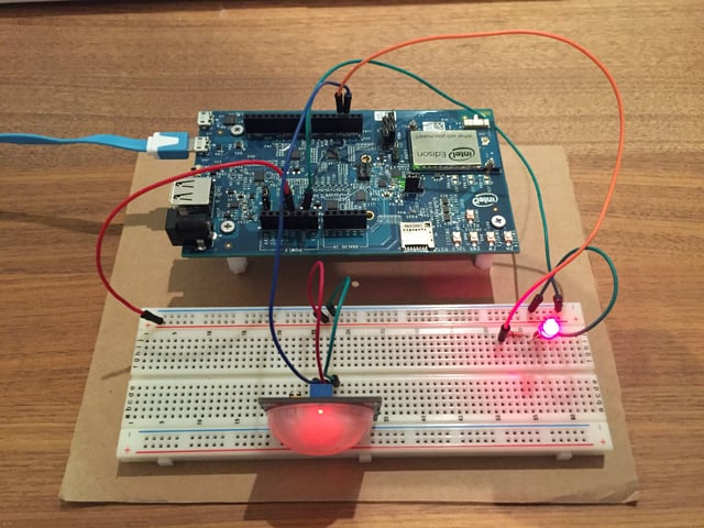
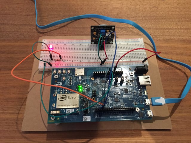
Got all that? Great! To start, we'll deal with the hardware side of things – getting things wired up to the Edison. Below is a picture of how my setup looks:

First, get ground and 5V wired down to the breadboard. In the photo above, you can see the red jumper line on the far left going from the 5V pin on the Edison breakout board to the breadboard. The green jumper line goes from one of the ground pins on the breakout board to the breadboard on the right. Next, run ground and 5V to the motion detector - you can see those as the green and red jumper wires in the middle of the breadboard. The inputs on the motion detector that I'm using are nicely labeled, having 4 pins labeled GND (Ground), VCC (the 5V input), OUT (the data we will be listening to in a moment), and EN (which we won't be using today, but can be used to turn the motion detector on or off). The OUT pin on the motion detector is wired to digital pin 2 on the breakout board (the blue jumper wire in the picture).
Next up: wiring the LED. We start from digital pin 3 on the breakout board (the orange jumper wire) and go to a resistor. Then we go from the resistor to the LED and from the LED to ground. If you haven't played with LEDs before, you might be wondering why we need a resistor at all – why can't we just run straight from the pin on the breakout board to the LED? Well, the problem is that most of the time, LEDs would like (or sometimes really need) a lower voltage than the voltage provided by a VCC or digital out pin. Adding an appropriate resistor drops that voltage to the voltage the LED expects. The digital out pins on the Edison breakout board output approximately 4.5V when high, so you can use that, plus the voltage range and expected milliamps for your LED, to determine the appropriate resistor. There are quite a few calculators for this on the web – I used this one. As a note, you generally don't need to be exact, just reasonably close (and going with too high of a resistor is always safer than too low). Most LEDs are pretty tolerant, especially red ones. In my case, I needed about a 180 ohm resistor, but I had a 200 ohm one laying around, so I used that one.
That's it for wiring this together – the important thing to remember is that the motion detector is attached to digital pin 2 and the LED is attached to digital pin 3. Before we jump into the code, though, you'll want to make sure that both your Edison and your WeMo outlet are happily attached to the same wifi network, since our code on the Edison will be talking to the WeMo over wifi. And you should probably plug in a lamp or light to the WeMo so you can actually see when things start to work. I suppose that counts as wiring things together, too – but now out of the physical world and into the ephemeral world of code!
Below is the code for the node app that will connect the motion detector to the WeMo outlet. I'll be going through it section by section.
So not really a huge amount of code, and a lot of that is because of two very helpful node modules:
Cylon is a great module for working with GPIO and various devices on the Edison. In this case, we'll be using it to read from the motion detector and toggle the LED. And wemo-client is a handy module for working with WeMo devices – we'll be using it here to turn on and off the WeMo outlet (and pay attention to the state of the outlet).
Probably the most annoying part of the code is actually finding the WeMo outlet:
The WeMo client has a discover function that will return each WeMo device it discovers (using UPnP). So we create a WeMo client instance and call discover, waiting for the device whose name is (in this case) "LosantOutlet_1". The name will be whatever you named your WeMo outlet when you set it up (probably with the WeMo phone app). Once we find it, we flip the stop variable, print out that we found the outlet, call the callback with the outlet device. However, about 25% of the time, it does not discover the outlet, and so we have to have code to retry the discovery – that is what the 5 second setTimeout call is about. If we haven't found the outlet within 5 seconds, mark the current discovery as stopped, and try again from scratch. It will do this over and over until it discovers the outlet, but assuming the outlet is actually on the network, it's almost always found by the third try.
I'm going to skip the middle section of code for the moment and tackle setting up Cylon next:
Almost all of this is just configuration information. First off, in the connections config blog, we have to tell Cylon that this is an Edison and that it should use the intel-iot adaptor. Then comes the part where we actually care about what pin numbers we plugged things into back when we were putting together the hardware. In the devices section, we first list the motion detector, which is on pin 2. We're just going to use the direct-pin driver (since all we need is to be able to detect high/low signals). Next we list the LED, which is on pin 3. Cylon has a driver specifically for LEDs: led. The key names (motionDetector and led) are essentially just the names we're giving these devices; they can be named whatever you want (and those names are how you would refer to them later). Finally, we give Cylon a reference to the function to run once everything is connected: in this case a function I've named cylonWork:
So this function runs once Cylon is started with a reference to the Cylon instance (off of which we can access the LED and the motion detector). The first thing we do, though, is call findOutlet so that we have the outlet available to manipulate. Once we have the outlet, we want to hook it up such that the LED reflects the state of the outlet. To do this, we hook into the binaryState event, which is fired whenever the outlet's state changes. The value passed to that ends up being the string '1' (for on) or '0' (for off). We convert that to a number and turnOn or turnOff the LED appropriately. The nice thing is that this will fire and change even if someone else changes the state of the outlet – or if you go and press the button on the outlet itself. So now the LED will always represent the state of the outlet: if outlet is on, the LED is on. If the outlet is off, the LED is off.
Now for the actual motion sensor. The direct-pin driver has a handy function called digitalRead, which will trigger every time the value of the pin switches between high or low and will hand the callback function the current value of the pin. If the value is 0 (no motion detected), we call setBinaryState on the outlet with 0 to turn the outlet off, and if the value is 1 (motion is detected), we call setBinaryState on the outlet with 1 to turn the outlet on.
Finally, the last line of the file:
This does exactly what you might think: it kicks everything off. Clylon gets set up and start running, which starts running the cylonWork method, and everything goes from there.
Here is an example of the output as the program runs:
root@edison:/usr/local/losant/examples# node edison-motion-detector-light.js
2015-12-17T00:26:53.279Z : [Robot 1] - Starting connections.
2015-12-17T00:26:53.302Z : [Robot 1] - Starting connection 'edison'.
2015-12-17T00:26:53.305Z : [Robot 1] - Starting devices.
2015-12-17T00:26:53.307Z : [Robot 1] - Starting device 'motionDetector' on pin 2.
2015-12-17T00:26:53.307Z : [Robot 1] - Starting device 'led' on pin 3.
2015-12-17T00:26:53.308Z : [Robot 1] - Working.
Found outlet!
No motion detected, turning off outlet...
Outlet has been turned off.
Motion detected, turning on outlet...
Outlet has been turned on.
No motion detected, turning off outlet...
Outlet has been turned off.
Motion detected, turning on outlet...
Outlet has been turned on.
No motion detected, turning off outlet...
Outlet has been turned off.
As you might expect, changing the state of the outlet using setBinaryState will eventually toggle the LED when the state of the outlet finally does change, and it's interesting to see the propagation time. In my setup, it generally takes about a tenth of a second between motion being detected and the physical outlet turning on, and then another three tenths of a second before that propagates back to the Edison and the LED is turned on.

And there you have it! You now have a motion detecting light (assuming you attached a light to the outlet). A next step could be to wrap this within a service so that you can get automatic process startup – or you might want to play around with the sensitivity of the detector, or add delays so that the outlet stays on for a longer time after motion is detected. Here at Losant, we had this by the door to the office for awhile, turning on a light in the office when someone was by the door. There are all sorts of things you can do, even with just this simple setup. If you have any questions or comments, feel free to leave them below, and I hope you enjoyed this little project!
