
What if I told you it was possible to build a security guard out of hardware, sensors, and the cloud? In this tutorial, we are going to walk through building a motion detector with an ESP8266 and a PIR sensor. Using Mongoose OS, the application firmware can be written in JavaScript. This tutorial will also demonstrate how to send that data to the Losant IoT Platform, where we can create a dashboard to monitor activity, and send alerts based on customizable rules.
If you would like a more generic example using Mongoose OS and Losant, check out this blog post: Getting Started With Mongoose OS, ESP8266, and Losant.
 Let's begin!
For this example, we are going to build a simple security guard for the Losant office. Its name is Officer Judy. We want Officer Judy to do two things:
- monitor the office for activity
- alert for suspicious activity
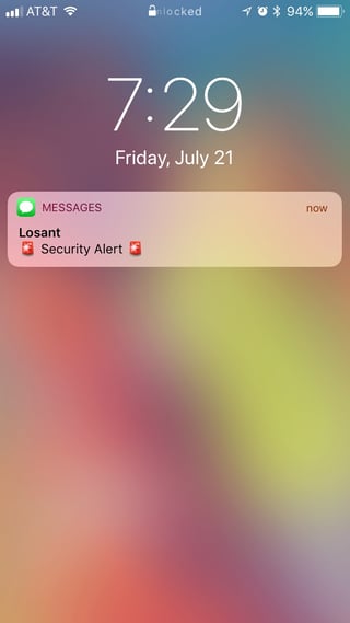
We can do this by capturing when there is, and isn't, movement in the office and send that data to Losant. Once in Losant, we can visualize the movement and build a workflow to alert ourselves.
Now that you have a high-level understanding of what we're building, we can create Officer Judy.
What You'll Need
To begin, you'll need a few things:
- Breadboard
- ESP8266 - NodeMCU
- PIR Sensor
- 3 Jump Wires
Wiring
To wire everything together, you should follow this schematic:
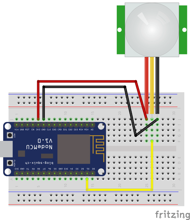
The PIR sensor typically has 3 leads attached: VCC, OUT and GND.
- Connect the VCC PIR sensor pin to a 3v3 pin on the NodeMCU.
- Connect the GND PIR sensor pin to a GND pin on the NodeMCU.
- Connect the OUT PIR sensor pin to a D1 pin on the NodeMCU.
Now, we are ready to configure the device firmware.
Code
The firmware for this example is available on GitHub. Open up your terminal, and clone the project:
$ git clone git@github.com:Losant/losant-mongoose-motion-sensor.git
In losant-mongoose-motion-sensor/fs/init.js is the main source code file—most of the interesting stuff happens here. Let's take a look:
load('api_config.js');
load('api_gpio.js');
load('api_mqtt.js');
load('api_timer.js');

// Set the pin number. On the NodeMCU D1 is pin 5.
// See pinout: https://pradeepsinghblog.files.wordpress.com/2016/04/nodemcu_pins.png?
let pirSensor = 5;

// Blink built-in LED every second
GPIO.set_mode(pirSensor, GPIO.MODE_INPUT);

// Look for motion every 2 seconds.
Timer.set(2000 /* 2 sec */ , true /* repeat */ , function () {
  let motion = GPIO.read(pirSensor);
  let topic = '/losant/' + Cfg.get('device.id') + '/state';
  let message = JSON.stringify({
   data: {
     movement: motion
   }
  });
  let ok = MQTT.pub(topic, message, 1);
  print('Published:', ok ? 'yes' : 'no', 'topic:', topic, 'message:', message);
}, null);
In this code, we are setting the pin number in a variable called pirSensor. If you want to use a different GPIO, make sure you update pirSensor. Then, we set the GPIO mode of pirSensor to be an input, which allows us to read the sensor data. Lastly, every two seconds, we read the GPIO data and send the data to Losant via MQTT.
As you can see, we are publishing on the topic:
'/losant/' + Cfg.get('device.id') + '/state'
Here, notice we are using Cfg.get('device.id') to create an MQTT topic. Mongoose has a configuration system that we can use to easily manage the config on our device. In losant-mongoose-motion-sensor/fs/conf1.json we have a base configuration file. It looks like this:
{
   "wifi": {
     "sta": {
     "enable": true,
     "ssid": "WIFI_SSID",
     "pass": "WIFI_PASSWORD"
   }
  },
  "device": {
     "id": "LOSANT_DEVICE_ID"
  },
  "debug": {
     "stdout_topic": "",
     "stderr_topic": ""
  },
  "mqtt": {
     "enable": true,
     "client_id": "LOSANT_DEVICE_ID",
     "user": "LOSANT_ACCESS_KEY",
     "pass": "LOSANT_ACCESS_SECRET",
     "ssl_ca_cert": "ca.pem"
  }
}
You must replace the following values:
- LOSANT_DEVICE_ID
- LOSANT_ACCESS_KEY
- LOSANT_ACCESS_SECRET
- WIFI_SSID
- WIFI_PASSWORD
You obtain the LOSANT_DEVICE_ID, LOSANT_ACCESS_KEY, and LOSANT_ACCESS_SECRET from Losant.
Losant
If you haven't already, sign up for a Losant account and create an application. Next, add a device to your Losant application for this project.
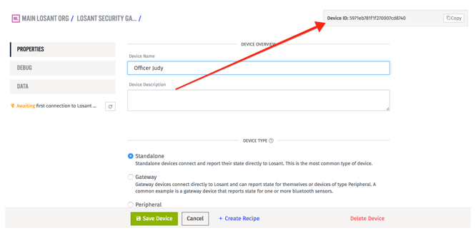
When you create the device, give it one attribute with the name "movement" and a type of "Boolean".
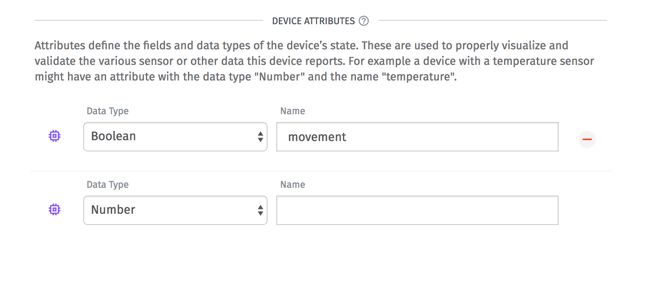
The "movement" attribute will represent the updates from the PIR sensor. Once you create the device, you will see the device ID; use this for LOSANT_DEVICE_ID.
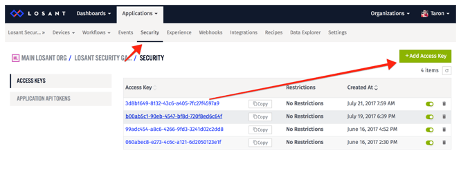
Next, obtain an Access Key and Access Secret. Select the "Security" tab in the dashboard and choose "Add Access Key".
Once you create, you will be given a key and secret:
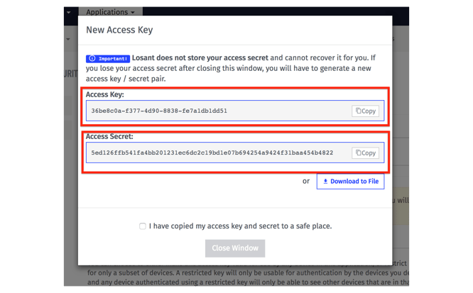
Now, you should update conf1.json and change the following values: LOSANT_DEVICE_ID, LOSANT_ACCESS_KEY, and LOSANT_ACCESS_SECRET.
Flashing
Now we are ready to flash our device.
The most important part of Mongoose OS is mos. Mos is a CLI tool. For this project, you must have the mos tool installed. For more info, see the mos installation instructions.
After mos is installed run these commands to build and flash the firmware:
mos build --arch esp8266
mos flash
Testing
Now, we need to test that everything worked.
From your terminal, you can see the logs of your application by running:
$ mos console
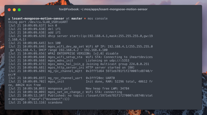
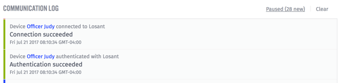
On the other end, if you go to your application overview page in Losant, you'll see your communication log. This gives you a ton of helpful information about what's happening in your application. Here you will be able to see successful connections:
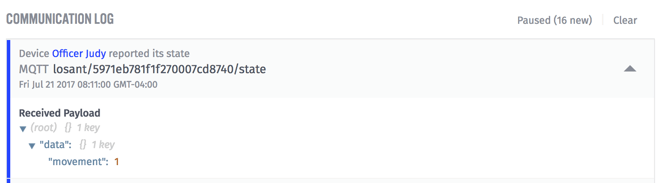
You'll also be able to see successful state updates:
If you run into any troubles, the first thing to check is your configuration and logs.
Dashboard
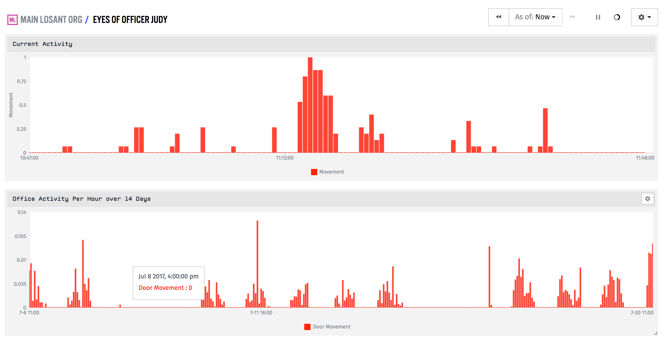
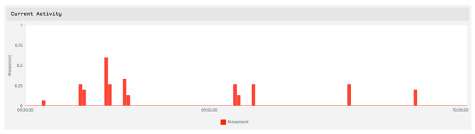
Having a security monitor wouldn't be complete without a dashboard. We are going to create one like this:
This dashboard shows two time-series graphs. The top shows the average movement, every 30 seconds, over the last hour. Since we are sending 0 or 1 to Losant every two seconds, the average we see on the graph will be somewhere between 0 and 1. On the graph, values closer to 1 means more movement, and vice versa.
The bottom graph is the same, but at a different resolution. It's the
With these two graphs, we get a good overall perspective of movement in the office. Officer Judy in action!
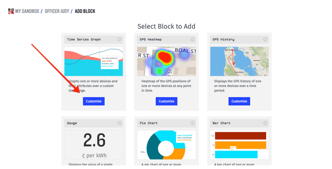
Now, let's make this dashboard. First create a dashboard, select "Add Block", and choose the Time Series Graph.
Next, you'll be able to configure the block settings. Give the block a header and choose your application. We'll be displaying historical data.

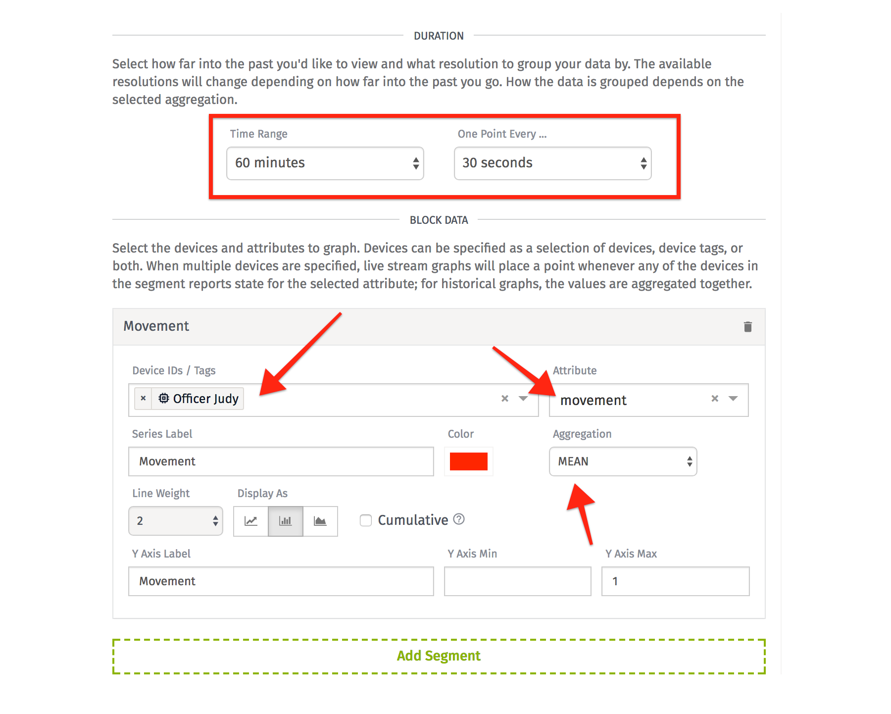
Now, here is the meat of the block settings. Let's reproduce the top graph first. We want to show the average movement, every 30 seconds, over the last hour. Set the "Time Range" and "One Point Every" appropriately. Next, select your device and the "movement" attribute.
Once you save this block (and collect some data), you'll have one block that looks like so:
Now, let's make the bottom graph. Since they are the same graph with different resolutions, if you go into the setting of the first block, you can clone it.
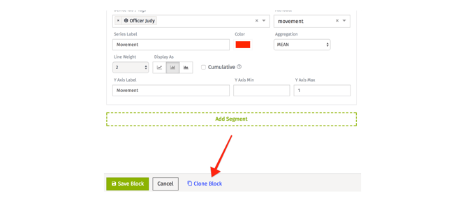
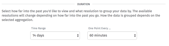
The only thing we need to change is the resolution. This second block will show the average movement, every hour, over the last 14 days. Set the "Time Range" and "One Point Every" appropriately.
Save it, and Voila! We have a dashboard.
What's Next?
Since we have the data in Losant, we can start to react to the data. For example, take a look at this workflow:
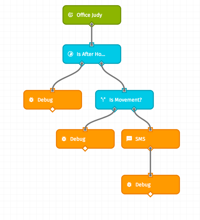
When we receive state from the device, this workflow will execute. It will check the time using the Time Range Node, which we can configure to check if the time is after hours. Next, we can check if that data point showed movement or not using a Conditional Node. Lastly, if there was movement, we can send a text message alerting us of suspicious activity. Officer Judy is in business.
Extra Resources:
If you build something awesome, please let us know in the forums or a comment below!