
The controllers found in most industrial equipment contain enormous reservoirs of untapped data. For OEMs pursuing IoT, this provides a unique opportunity. All of this equipment (CNC machines, generators, air compressors, etc.) already contain dozens of sensors that are constantly being read by the controller as part of normal operations. Finding a way to access and centralize this existing sensor data is a huge step towards the ultimate goal of offering IoT services like remote monitoring or condition-based maintenance.
Modbus is a common protocol that exists in many industrial controllers and allows you to quickly tap into your equipment's existing source of valuable data.
Modbus has two common communication options: TCP and RTU. This tutorial provides step-by-step instructions for how to use Modbus RTU. MQTT is then used to report that data to a centralized IoT platform. For this example, the platform I'll be using is Losant. If you'd like to follow along, Losant provides a no-cost Developer Sandbox that can be used for testing and prototyping.
The Components
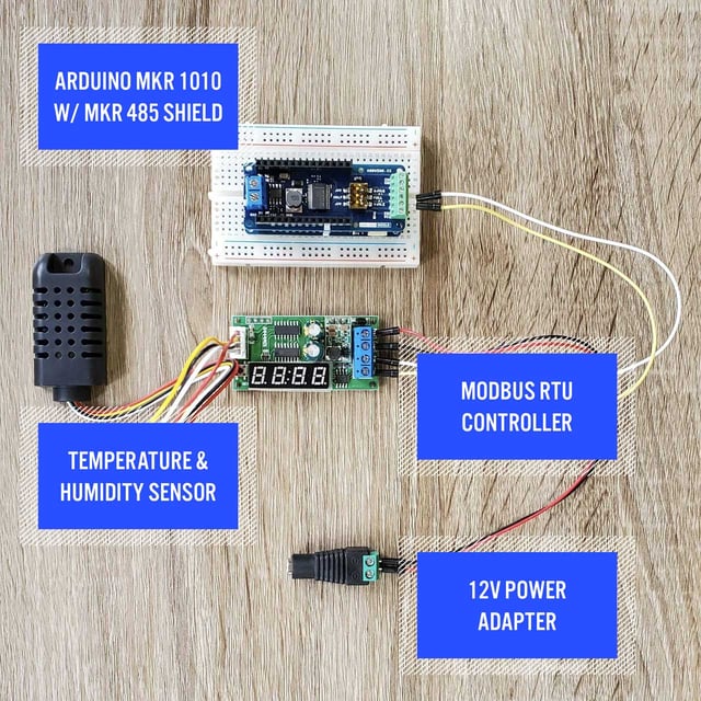
For the Arduino board, I'll be using the MKR WiFi 1010. Although Arduino boards are not currently a popular choice for production deployments, they are an excellent option during the prototyping and proof-of-concept stage. In order to access the Modbus RTU interface, which in my case is exposed over RS-485, I'm using the MKR 485 Shield.
To reduce the complexity of this tutorial, while still interfacing with an actual Modbus RTU controller, I've decided to use this RS-485 Modbus RTU Humidity and Temperature Sensor.
Here's an image of my complete setup:
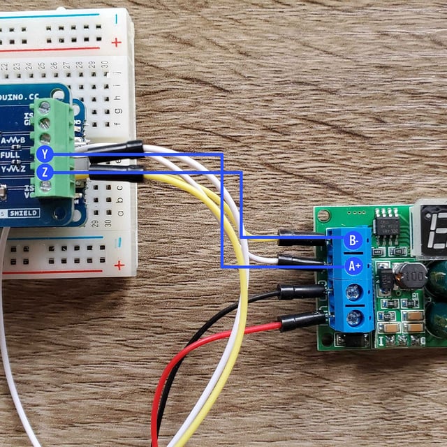
Wiring the Modbus RTU Controller to the MKR 485 Shield
The Modbus RTU controller involves two wires whose terminals are labeled "B-" and "A+". The MKR 485 Shield supports both standard and full-duplex modes, so you'll see four available wiring terminals. When using just two wires, the terminals to use on the shield are "Y" and "Z". This means "A+" on the controller is connected to "Y" on the shield and "B-" on the controller is connected to "Z" on the shield.
Reading Modbus RTU From Arduino
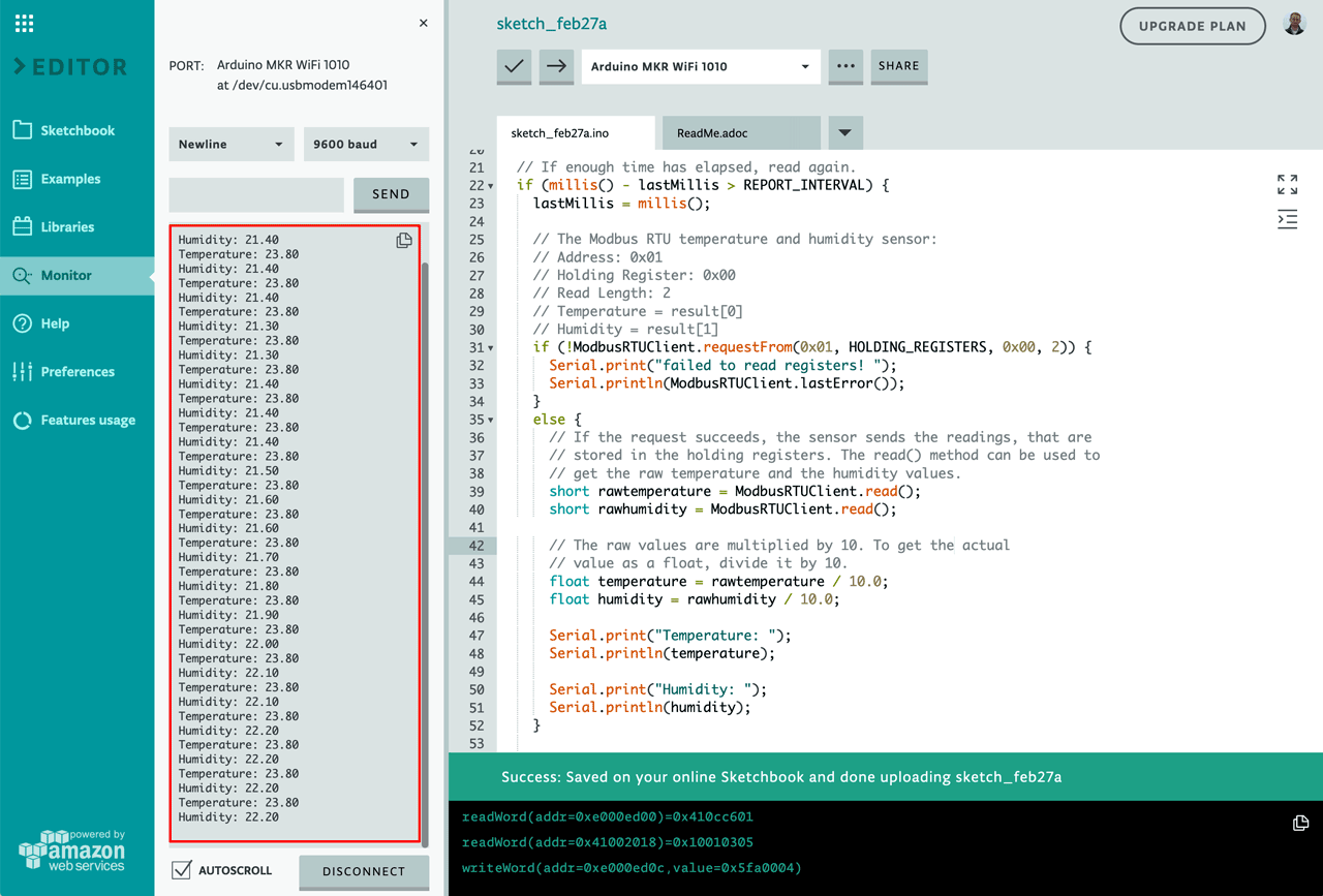
Before we can send any data to an IoT platform using MQTT, we must first read it from the Modbus controller. This is the code I'll be using:
This sketch reads the temperature and humidity values from the Modbus controller once per second, then prints those values to the serial monitor. Most of the heavy lifting is done by the Arduino Modbus library. This library can act as both a Modbus server or a Modbus client. In this scenario, the controller is the server and the Arduino is the client. Using this library can be distilled down to the following snippets:
ModbusRTUClient.begin(9600)
The begin function initializes the underlying serial connection to the Modbus controller. This function accepts numerous optional parameters (e.g., baud rate, parity, stop bits, etc), and the parameter values you provide are based on your controller's specific configuration. The controller I'm using is configured with the default values provided by the Arduino Modbus library, so the only thing I'm required to provide is the baud rate (9600).
ModbusRTUClient.requestFrom(0x01, HOLDING_REGISTERS, 0x00, 2)
The requestFrom function performs the underlying serial communication to read the specific Modbus values. This configuration will almost certainly be different for each controller. Here is a list of what each value represents for this specific controller:
- 0x01—The address of the controller. Modbus operates on a bus, which means there could be multiple controllers at different addresses. The controller I'm using has a hard-coded address set to 0x01. Your controller may have a different address and in many cases the controller will allow you to change it.
- HOLDING_REGISTERS—Modbus supports many different functions. Which functions are supported is entirely up to your controller. In my case, the controller places the values of the temperature and humidity sensors in holding registers, which I can read.
- 0x00—The address of the holding register I'd like to read. Controllers can place any number of values at any number of addresses. It's not uncommon for industrial controllers to expose hundreds of values across hundreds of addresses.
- 2—The number of registers to read, starting at the previously specified address (0x00). My controller uses two registers, one for temperature and one for humidity.
short rawtemperature = ModbusRTUClient.read()
short rawhumidity = ModbusRTUClient.read()
The read function is used to receive the values for each requested register. Since I requested two registers (address 0x00, length 2), I need to call the function twice to get both values. In almost all cases, a Modbus register is returned as a 16-bit value. Whether that value is signed or unsigned is up to the controller. In my case, the values are signed, which means I can get both positive and negative values.
float temperature = rawtemperature / 10.0
float humidity = rawhumidity / 10.0
Since Modbus registers can only represent integer values, it's common to receive them in a raw format that needs some level of transformation. For my controller, the values are multiplied by ten. This means I can divide them both by ten to get one decimal point of precision (e.g., 236 -> 23.6 degrees C).
Now that the data is successfully being read, we can print them to the serial monitor.
Using MQTT to Send Modbus RTU Data to an IoT Platform
MQTT has become a popular choice for device-to-cloud communication. Almost any IoT platform you use will offer an MQTT broker that your devices can connect to. For this tutorial, I'm using Losant's MQTT broker.
To do the MQTT communication itself, I'll be using the arduino-mqtt library. Losant does provide a wrapper library, but for this tutorial I wanted to demonstrate using MQTT directly.
For WiFi communication, I'm using the WiFiNINA library, which is supported on the Arduino MKR WiFi 1010 board that I'm using. You may require a different WiFi library, based on the specific Arduino board you're using, however they all work in very similar ways. For information on configuring WiFi, see Arduino's documentation for your specific WiFi library.
Here's the updated source code that adds all of the MQTT communication:
Below are the main components that are involved with communicating over MQTT:
// MQTT credentials.
const char* MQTT_CLIENT_ID = "mqtt-client-id";
const char* MQTT_USERNAME = "mqtt-username";
const char* MQTT_PASSWORD = "mqtt-password";
MQTT authentication supports three fields: a client ID, a username, and a password. When connecting to Losant's MQTT broker, the client ID is the ID of the Losant Device, and the username and password are an access key and secret.
mqttClient.begin("broker.losant.com", 8883 /* secure */, wifiClient)
This line sets up the connection to the MQTT broker. It accepts a URL (broker.losant.com), a port (8883), and the network client that's used for the underlying communication. The network client in my example is a WiFiSSLClient. The URL and port are specific to your IoT platform. In most cases, MQTT uses port 1883 for unencrypted communication and port 8883 for encrypted communication. Encryption is always recommended if your board supports it.
mqttClient.connect(MQTT_CLIENT_ID, MQTT_USERNAME, MQTT_PASSWORD)
This line attempts the actual connection to your MQTT broker. Once this succeeds you're ready to publish data. The MQTT specification does not provide helpful error messages if any of these credentials are incorrect, so it's very important to double-check your information.
char topic[100];
char payload[100];

// The MQTT topic to publish to.
sprintf(topic, "/losant/%s/state", MQTT_CLIENT_ID);

// The payload data as a JSON object.
sprintf(payload, "{ \"data\": { \"temperature\": %.1f, \"humidity\": %.1f }}", temperature, humidity);

mqttClient.publish(topic, payload);
After I read the temperature and humidity values from the Modbus RTU controller, they can now be sent to our MQTT broker. Losant has a special MQTT topic for Device State, which will automatically record this data on Device Attributes and put them into a time series database. The topic, however, can be anything that your broker supports.
MQTT doesn't enforce any specific data format for the payload you send. Since I'm publishing to Losant's special state topic, I have to format the data as a JSON object with fields for each attribute I'm sending, which in this case are temperature and humidity.
The publish call is then used to report the data to the MQTT broker.
Use Modbus RTU Data for IoT Solutions
Now that your Modbus RTU data is being received by your IoT platform, you can develop the specific IoT solution that your organization is pursuing. That could be machine-as-a-service, real-time equipment monitoring, condition-based-maintenance, or many others.
Losant is an application enablement platform, which means it provides much more capability beyond simply ingesting data over MQTT. With built-in dashboarding, data analytics, a real-time workflow engine, and the ability to create and publish end-user experiences, Losant provides a complete technology foundation for organizations seeking ways to accelerate their IoT strategy.

Losant offers a no-cost Developer Sandbox so you can build the example in this tutorial or any other proof of concept projects at your own pace. If you have any questions or comments about the material discussed, let us know in the Losant Forums.