This Thanksgiving our family did what any good family of "technology enthusiasts" would do - we made our own LED dice roller using an Arduino. The inspiration came after an intense game of Monopoly, and if you've ever played Monopoly then you know dice rolling is a pretty integral part of the game.
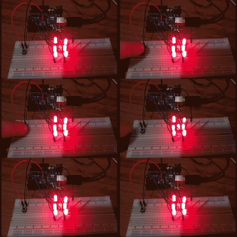
As you can see from the animation above, our dice is made up of seven LEDs, a button, and an Arduino Uno. When you push the button the dice "rolls" for a bit then lands on a random number. This tutorial describes how to properly connect the LEDs to the bread board, how to debounce the button clicks, and how to randomly pick a dice number t0 create the roll animation. Note: A few weeks ago I wrote about getting started with Intel's Edison so I thought we'd spend some time with Arduino this week.
Getting Started With the Arduino
Using the Arduino is simple and only requires a few steps to get up and running.
1. Download the Arduino IDE
The first thing you'll have to do is download the Arduino IDE for your specific operating system. Currently it supports Windows, Mac, and Linux.
2. Connect the Arduino
Different Arduino's use different USB connectors, so make sure you have the correct cable. I'm using the Arduino Uno, which requires a USB B-Type cable. If your Arduino has multiple USB ports, like the Zero, connect it to the one labeled "program". Arduinos are powered over USB, so once it's connected some LEDs should light up.
3. Run the Arduino Blink Example
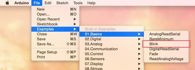
The Arduino IDE comes with an example that simply blinks one of the built-in LEDs. It's a good way to test and make sure everything is properly connected. Launch the Arduino IDE and select the blink example from File > Examples > 01.Basics > Blink.
The next thing you need to do is tell the Arduino IDE what kind of board you have. This is done through the Tools > Board menu.
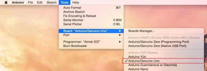
Since I'm using an Arduino Uno, that's what I selected. If you're using a board that is not listed by default, like the Zero, there may be special instructions required to properly setup the board. Please refer to the specific instructions provided by Arduino for more details.
The next thing we have to do is tell the Arduino IDE what port the board is plugged into. This is done using the Tools > Port menu.
 On Macs the port will be named something like "cu.usbmodem". Select the appropriate port from the list. On other operating systems, it will be named differently. Refer to the Arduino documentation for details.
Now that everything is properly configured, you can click the Upload button on the blink example to flash the Arduino with the blink code.
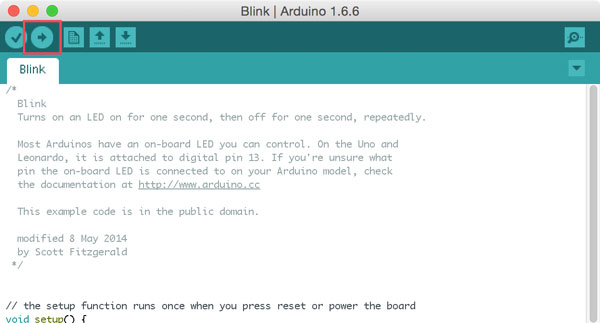
After a few seconds, a small orange LED on the Arduino board will be blink once a second. If this works, then everything is configured properly and you're ready to go.
Connect the LEDs and Button
In order to represent all possible sides of a dice, you need seven LEDs. There are some clever ways to combine LEDs on the same Arduino output, because several dice rolls light the same LED, but for simplicity we're just going to connect each LED to a separate output.
Laying out the LEDs on a breadboard is a little challenging because no LEDs can share the same row (if they did, then they'd all light up at the same time, which isn't what we want). This is simple to get around by bending the leads a little so each LED has its own row for the voltage. Here's a close up of my breadboard to show how they're all connected.
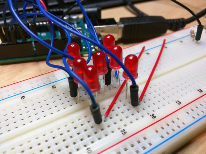
As you can see, I've bent a few of the LEDs so that they don't share the same voltage inputs. They can however all share the same ground connections. Below is a wiring diagram showing all of the connections without the grounds.
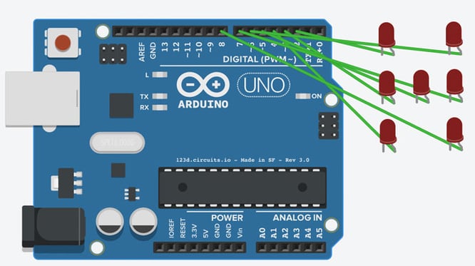 As you can see I've connected my LEDs to the digital pins 2-8. This allows me to individually turn on each LED by writing a HIGH to each of those pins.
Now we need to connect the button so we can roll the dice when it's pushed. Here's an image of the layout I used.
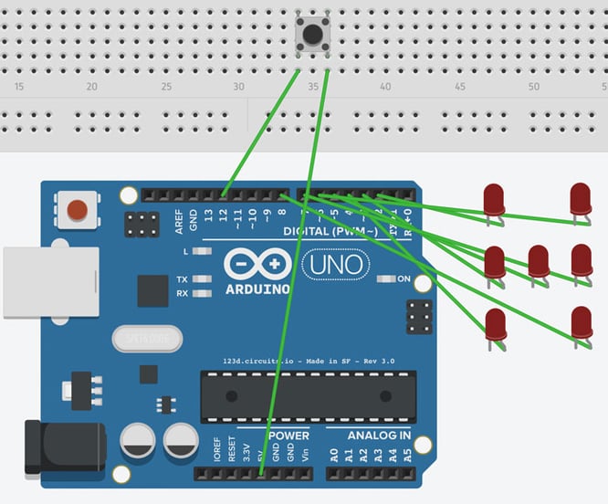
Connecting a button is pretty simple. I have the Arduino's 5V output connected to one side and the other side is connected to one of the digital pins. This way whenever the button is pressed I will read it as a HIGH on pin 12.
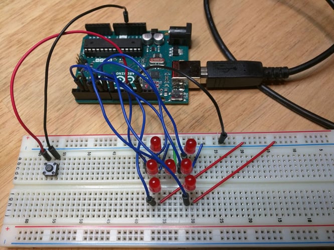
Here's an actual image of all of my connections.
Write Some Code
Now that everything is connected, it's time to write some Arduino code to control the lights. I'm going to start by posting all of the code up front, then go through and describe each section in detail.
Let's begin by looking at all of the initialization code at the top of the file.
This code is setting up all of the pins so they can be easily referenced later in the application. The first part defines which physical pin each LED is connected to. For mine, the LEDs are connected to pins 2-8. Next I simply put these pins in an array so I can easily iterate over them. After that I make six arrays that represent the lights needed for each corresponding dice roll. I then make an array of these arrays so I can easily reference the needed lights. The "rolls" array maps directly to a dice number, so if I roll a zero (which corresponds to a one), I can simply index this array at zero, which returns the array of lights to actually light up. This makes later code a lot easier to work with.
Next, let's look at the setup() function.
This code is very simple. The first thing I do is make the button pin an input so I can read whether it's pushed or not. The only other thing I do is set all the LED pins as outputs.
Next up is the loop() function. This is the most complicated, but that's only because nearly all of the code is used to debounce the button click.
The debounce code comes from Arduino's tutorial and I recommend reading that for more details. The reason we have to debounce the button is that the circuit is not an instant on/off. The button works by physically connecting two wires. There's a moment when the wires are close together but not solidly connected where the button will bounce very rapidly between on and off. Once the button is fully pressed, the connection is solid and it will stop bouncing. The debounce logic works by waiting until the same value is returned by the button for a minimum amount of time, in this case 50 milliseconds. Once that happens we can trigger our action, which is to shuffle() and then roll() the dice.
Let's first check out the roll() function, which picks a random number and lights up the correct LEDs.
The first thing we do is pick a random number between 0 and 5. We then grab the array of pins to light from the rolls array defined at the beginning of the file. The next thing we do is turn off all LEDs and then turn on the LEDs required to represent this dice roll.
Now let's take a look at the shuffle() function, which creates a random animation to simulate the dice "rolling".
The shuffle function is surprisingly easy. Since we already have a function to pick a random number and light up the LEDs, all we need to do is call that function a bunch of times. In this case I call it 25 times with a 40 millisecond delay in between.
And with that you've got a fully functional dice roller with an Arduino Uno, a button, and seven LEDs. Download on GitHub here.
