
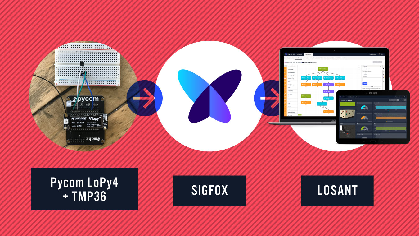
Pycom makes a series of development boards that provide a quick, easy, and affordable way to get started with your IoT project across a wide variety of communication protocols. This article provides a step-by-step guide for how to use a Pycom LoPy4 to read temperature data from a TMP36 sensor and report it to the Losant Enterprise IoT Platform using Sigfox connectivity.
How to Set Up the Pycom LoPy4 Board
Please follow Pycom's detailed instructions for how to set up the board. This tutorial will assume you also have an Expansion Board, which makes it easy to power, program, and access the I/O pins. You'll also need an external antenna in order to communicate with the Sigfox network.
After you've followed the hardware setup guide, install the required software. This tutorial will be using the Pymakr Plugin for Visual Studio Code in order to program the device itself.
After you've got the required software installed, please follow Pycom's guide on making your first Pymakr project. Once you've got your first application working, you're ready to continue this tutorial.
How to Register a Sigfox Device
In order for your device to communicate over the Sigfox network, it must first be registered. Follow Pycom's guide on how to register your LoPy4 device.
How to Wire the TMP36
The TMP36 has three leads. One is power, one is ground, and one is the analog signal. Adafruit provides a detailed TMP36 guide if you'd like to dig deeper. With the flat side facing you, power is on the left, signal is in the middle, and ground is on the right.
 Image courtesy of Adafruit.
Pycom provides a nice wiring diagram for the LoPy4, which can help you identify which pins provide analog inputs. For this tutorial, we're going to use P16 as our input, which is labeled G3 on the expansion board.
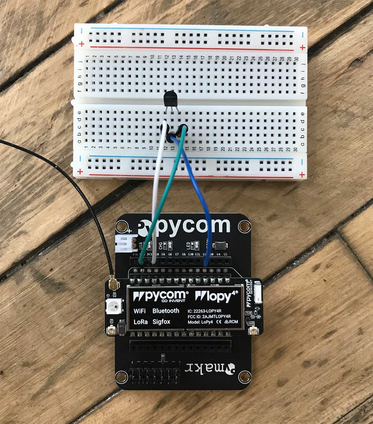
With the flat side of the TMP36 facing you, make the following connections:
- Connect G3 (P16) on the expansion board to the middle pin on the TMP36.
- Connect 3V3 on the expansion board to the left pin on the TMP36.
- Connect GND on the expansion board to the right pin on the TMP36.
How to Read the TMP36 Value
The first program we'll flash to the LoPy4 will simply read the TMP36's temperature value every second and print it to the console. This will be useful to determine whether or not you've got everything wired correctly.
Fortunately, this code is very straightforward. Below is the entire program.
import machine
import time

adc = machine.ADC()
apin = adc.channel(pin='P16')

while True:
  millivolts = apin.voltage()
  degC = (millivolts - 500.0) / 10.0
  degF = ((degC * 9.0) / 5.0) + 32.0

  print(millivolts)
  print(degC)
  print(degF)

  time.sleep(1)
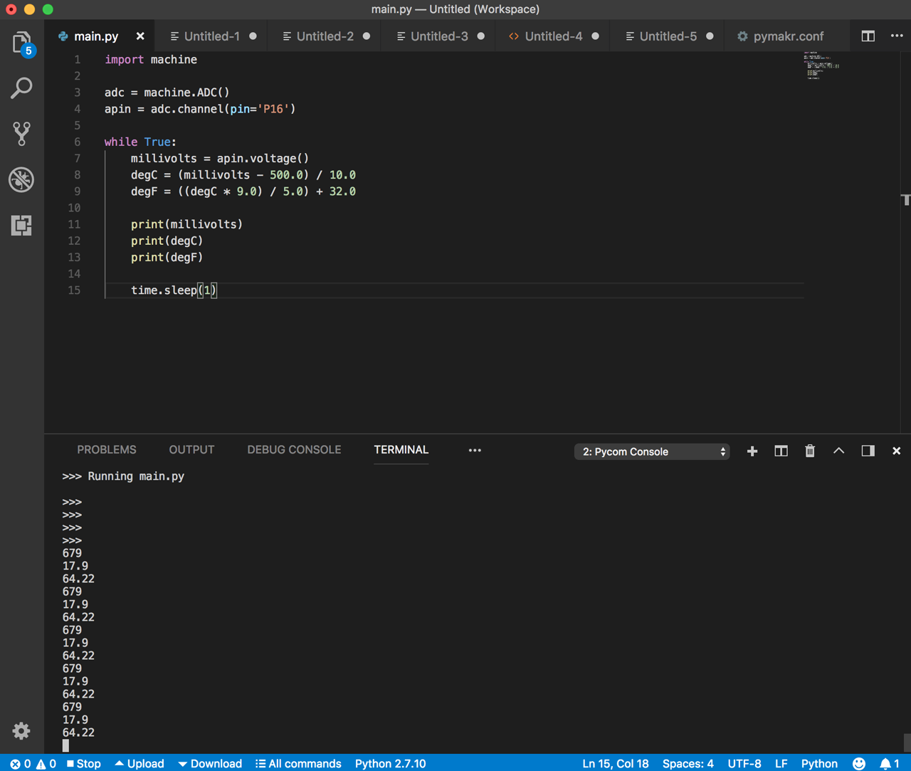
The first two lines are configuring the analog input on P16. We then have a loop that repeatedly reads the analog input and prints its value. According to the TMP36's datasheet, the voltage it reports can be converted to Celsius using the formula (millivolts - 500) / 10. The next line is simply converting Celsius to Fahrenheit. We then print the raw voltage and temperature values to the console.
When you run this on the LoPy4, you'll see the following output in your console.
How to Report TMP36 Temperature Data to Sigfox
Now that we have the TMP36 sensor being read, it's time to send the data to Sigfox. Sigfox, being low power, only transmits small chunks of information every few minutes. Sigfox has a maximum message rate of 140 per day. This means we can send a data point roughly every 15 minutes.
Below is the updated code that sends our temperature data to Sigfox:
The new code at the top is initializing the network connection to Sigfox. Refer to Pycom's Sigfox documentation for more details. The important thing to pay attention to is the Sigfox zone, which is configured for RCZ2 in the example above (USA). Based on your geographical location, you'll have to change this accordingly. The table of Sigfox zones and their corresponding locations is below.
| Zone | Locations |
| RCZ1 | Europe, Oman, South Africa |
| RCZ2 | USA, Mexico, Brazil |
| RCZ3 | Japan |
| RCZ4 | Australia, New Zealand, Singapore, Taiwan, Hong Kong, Columbia, Argentina |
The actual code to send data to Sigfox is the following:
raw = bytearray(struct.pack("f", degC))
s.send(raw)
Sigfox works by sending a maximum of 12 bytes on each transmission. The first line is converting our temperature floating point value to raw bytes. The next line is simply sending those bytes to Sigfox.
The only other modification was to increase the sleep from 1 second to 900 seconds (15 minutes).
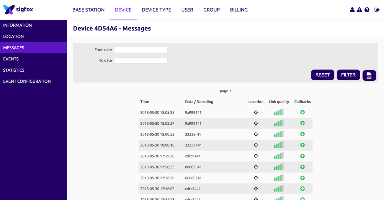
Once you run this code, you can verify data is being received by inspecting this device's messages in the Sigfox backend.
How to Create a Sigfox Callback
Sigfox takes care of transmitting data from the device to their cloud backend. Once the data is received by Sigfox, if you want to use it in a meaningful way, you'll have to forward it somewhere else. That's where Losant comes in.
The Losant IoT application enablement platform provides an easy-to-use service to visualize, react, and build end-user experiences on top of your Sigfox data. If you don't already have a Losant account, sign up for a free developer sandbox.
Sigfox can forward messages to other services by using a callback. Callbacks accept a webhook URL, and whenever a message is received by a Sigfox Device Type, it will be forwarded to that webhook.
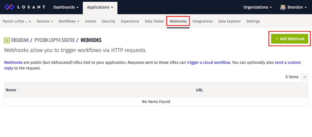
Losant makes it very easy to create webhooks that can be invoked by the Sigfox backend. If you don't already have a Losant application, feel free to create one now. Webhooks in Losant can be created under the main application "Webhooks" menu. Once there, click the "Add Webhook" button to create a new webhook.
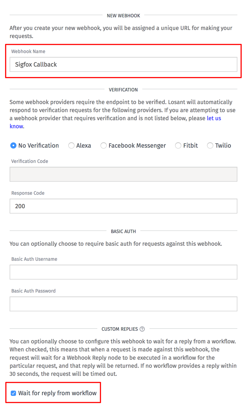
You can name the webhook anything you'd like. Make sure to also check the "Wait for reply from workflow" checkbox. When Sigfox invokes a webhook, it expects a reply that indicates the message was successfully received. Within Losant, webhooks can trigger a workflow. We'll use this workflow to reply when we're done handling the Sigfox data.
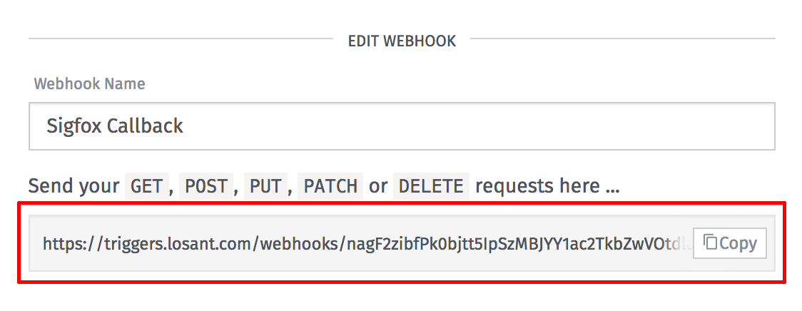
Once you click "Create Webhook" at the bottom, you'll be presented with your unique webhook URL. Copy/paste this somewhere convenient because we'll need to provide it to the Sigfox backend.
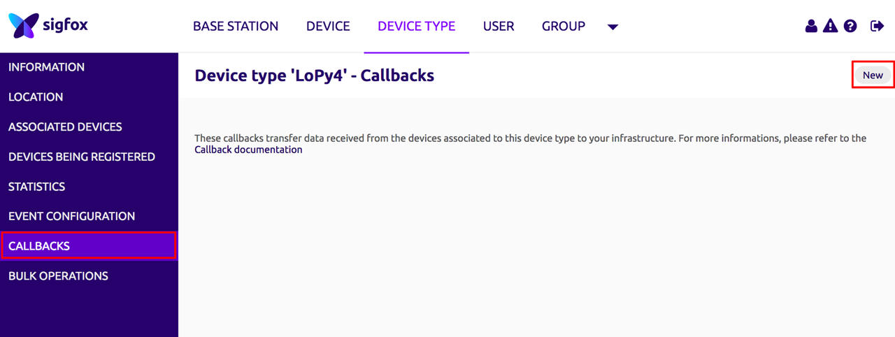
Next, log into the Sigfox backend, navigate to your Sigfox Device Type page, select the Callbacks menu, and then click the "New" button on the top right.
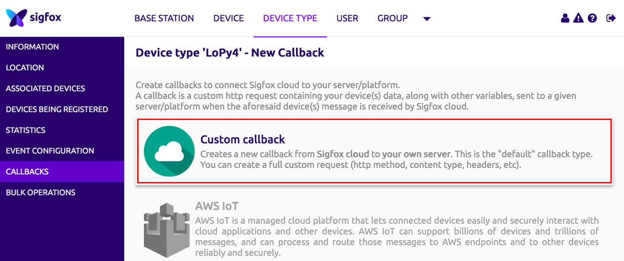
At the top of the following page, select "Custom callback" from the list.
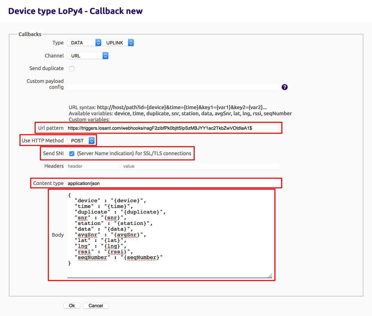
For this custom callback, set the following configuration values:
- Set the "Url pattern" to the webhook URL you obtained from Losant.
- Set the "Use HTTP Method" to "POST".
- Check the "Send SNI" checkbox.
- Set the "Content type" to "application/json".
- Set the body to the following:
{
  "device" : "{device}",
  "time" : "{time}",
  "duplicate" : "{duplicate}",
  "snr" : "{snr}",
  "station" : "{station}",
  "data" : "{data}",
  "avgSnr" : "{avgSnr}",
  "lat" : "{lat}",
  "lng" : "{lng}",
  "rssi" : "{rssi}",
  "seqNumber" : "{seqNumber}"
}
You can change this body if you'd like, but this is a useful set of default variables provided by Sigfox. The most important field is "data", which includes the raw temperature bytes that our Pycom board is transmitting.
Once you click "Ok", this callback will be saved and Sigfox will begin forwarding your device's messages to the Losant webhook.
How to Parse and Store Sigfox Data
Now that data is being forwarded from the Sigfox backend to your Losant webhook, we need to create a Losant Workflow to parse the temperature data and record it onto a Losant device.
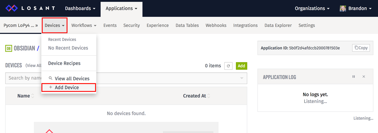
First, create a new device to represent your Pycom board. You can do this by clicking the main "Devices → Add Device" application menu.
On the next screen, choose to create a "Blank Device".
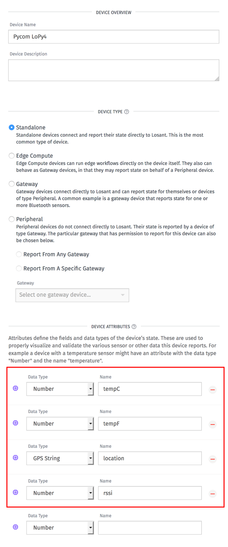
You can name the device anything you'd like. The only thing you'll have to configure are the attributes. Attributes describe what data Losant will store for this device. The first two attributes in the example above are for the temperature in Celsius and Fahrenheit. The location and rssi (signal strength) attributes are provided automatically by Sigfox. Feel free to add the other variables configured in the Sigfox callback body if you'd like.
After clicking "Create Device", we now have a device that can be used to store our Sigfox data.
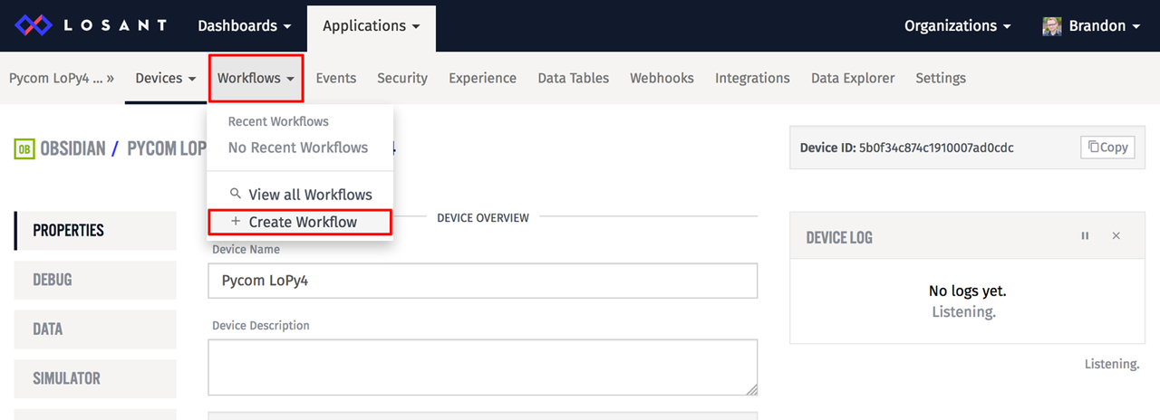
Next we need a workflow to handle the incoming Sigfox data, parse it, and record it on to our newly created device. Create a new workflow by clicking the main "Workflows → Create Workflow" application menu.
On the next screen, select "Create Cloud Workflow". Losant also supports Edge Workflows, which are executed on gateways that have the Edge Agent installed. Since Sigfox will be invoking a webhook on Losant's cloud, we need a cloud workflow to trigger on those requests. You can name the workflow anything you'd like.
Once the workflow is created, you'll be presented with an empty canvas.
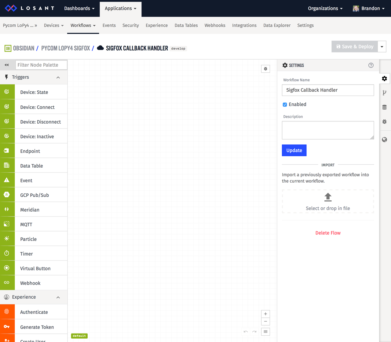
Since we want this workflow to trigger whenever Sigfox invokes our webhook, start by dragging a Webhook Trigger onto the canvas.
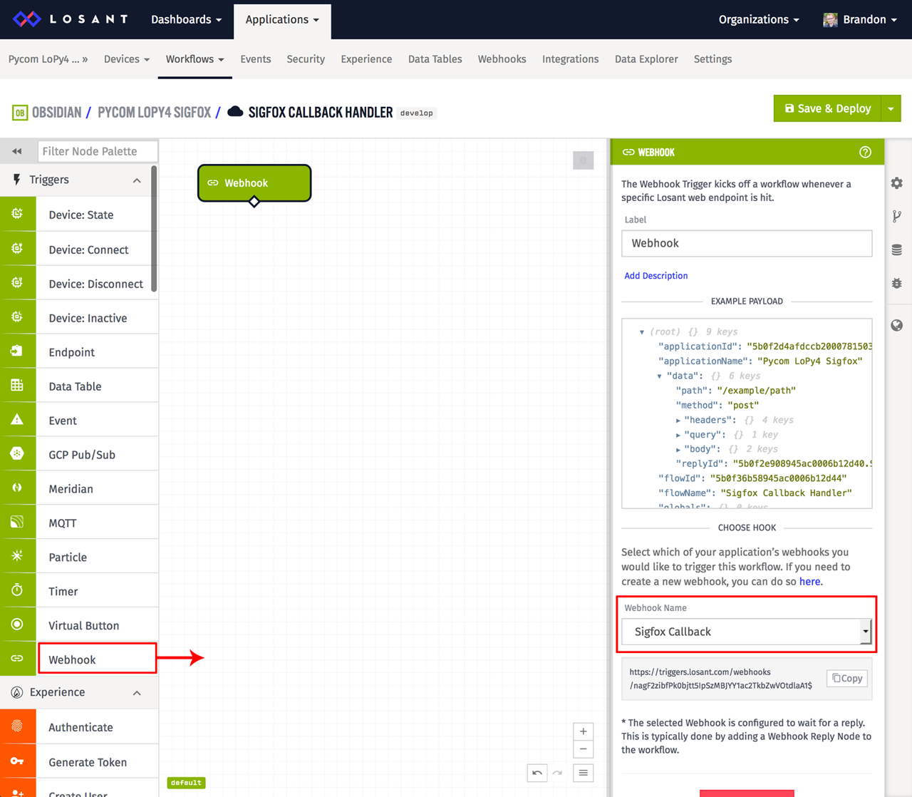
The only required configuration for this node is to ensure the webhook you created earlier is selected in the drop down. If you only have one webhook, it will be selected by default.
Next, drag a Debug Node onto the canvas and attach it to the Webhook Trigger. We'll use this node to inspect the incoming data and make sure Sigfox is properly configured to invoke our webhook.
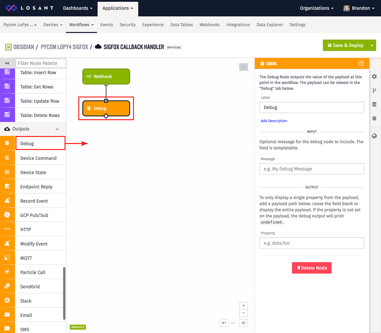
This node does not require any configuration. Debug Nodes work by printing the current workflow payload in the debug tab whenever it's executed by the workflow.
Next, add a Webhook Reply Node so we can reply back to Sigfox and indicate we've successfully received the message.
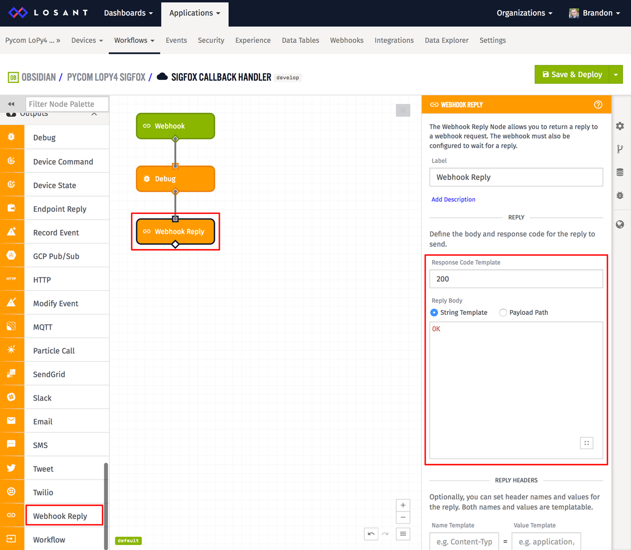
Configure this node to respond with a status code of 200 (HTTP OK) and with a body of "OK". This is all that's needed for Sigfox to know we've successfully received the message.
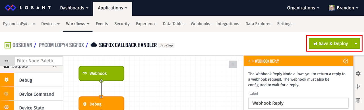
We can now test this workflow by clicking the "Save and Deploy" button at the top.
With the workflow successfully deployed, we can now see the data forwarded by Sigfox in the workflow's debug tab.
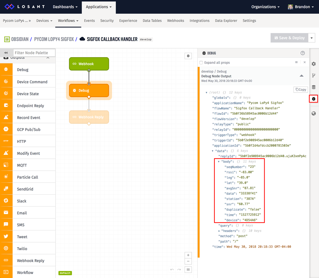
As you can see, the data in the workflow payload is formatted exactly as you specified in the Sigfox callback body. Now that the data is coming in, it's time to convert the raw bytes back to a temperature value and store it on our newly created device.
First, start by inserting a Function Node between the trigger and the Debug Node.
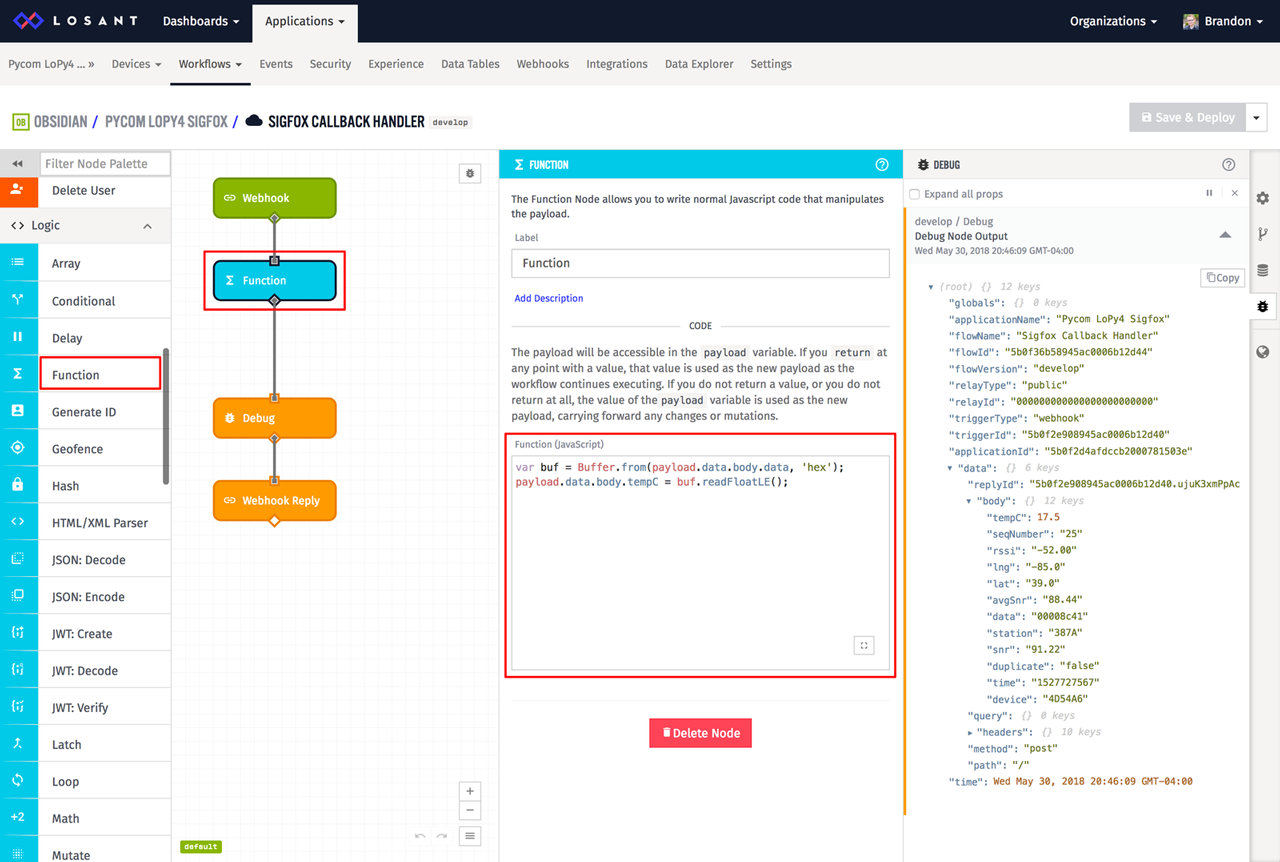
The Function Node provides a way to execute arbitrary JavaScript code. Since Sigfox data can be packed or encoded in any way, the Function Node is a good way to convert the raw data back into something readable. In this example, the data is simply a float that's been encoded to raw bytes. The code to unpack it is the following:
var buf = Buffer.from(payload.data.body.data, 'hex');
payload.data.body.tempC = buf.readFloatLE();
The first line is creating a Buffer from the raw hexadecimal string provided by Sigfox. Within the function node, the current workflow payload is automatically available on the payload variable. You can tell from the debug output that the raw Sigfox data is on the payload at data.body.data, which means we need to pass payload.data.body.data to the Buffer.from function.
The second line is reading a float from that buffer using the readFloatLE function. This function converts the raw bytes back into a floating point number. We're saving our converted temperature value back on the payload at data.body.tempC so that nodes that execute after this one will have access to our new data.
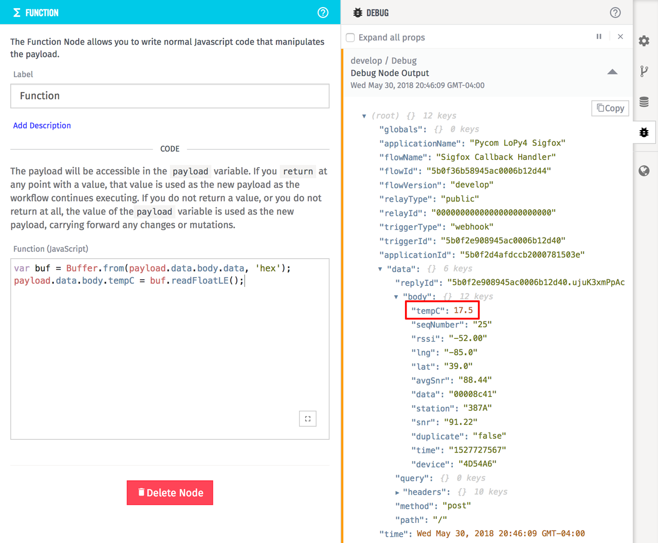
If you save, deploy, and receive a Sigfox message at this point, you'll see the tempC variable added to the payload.
If you recall from the device attributes we configured earlier, we also need the temperature in Fahrenheit. Add a Math Node after the function node to calculate the temperature in Fahrenheit from the Celsius value we already have.
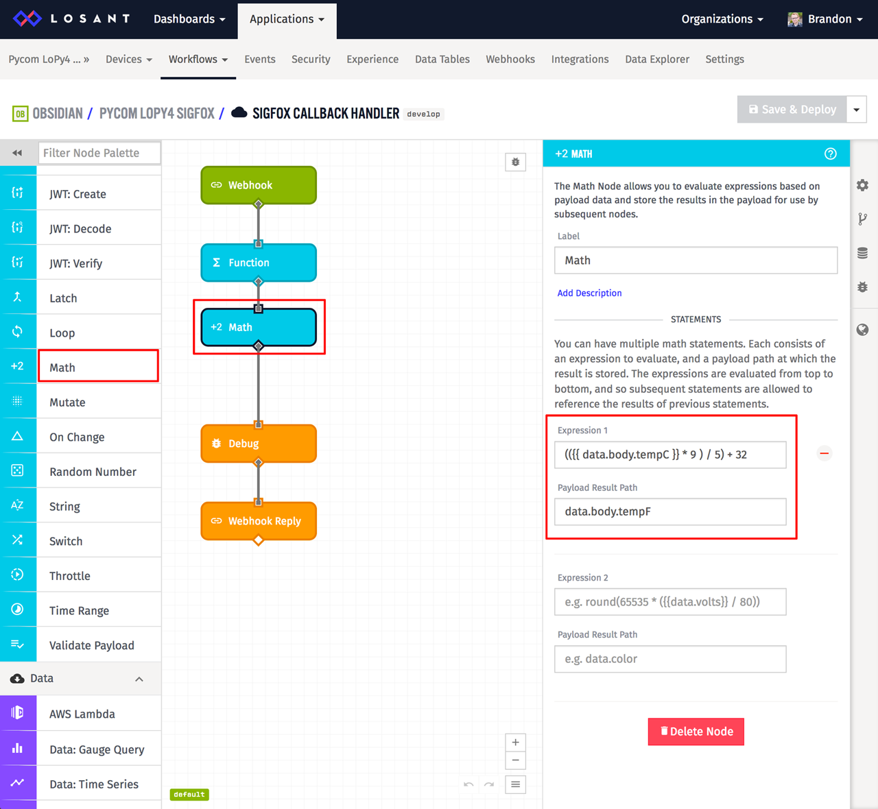
Math Nodes provide a way to execute mathematical expressions and put the result back on the payload. For this example, the expression is the basic formula to convert Celsius to Fahrenheit.
(({{data.body.tempC}} * 9 ) / 5) + 32
This field is demonstrating a use of what Losant calls a template. Templates, which are expressions surrounded by double curly braces, allow us to access information on the payload.
When this node executes, whatever is on the payload at data.body.tempC will be inserted into this expression, evaluated, and the result will be placed back on the payload at data.body.tempF.
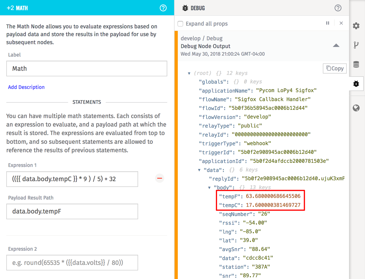
If you save, deploy, and receive a Sigfox message now, you'll see both tempC and tempF on the payload.
The last thing this workflow needs to do is save this information to our device. Add a Device State Node to the workflow canvas.
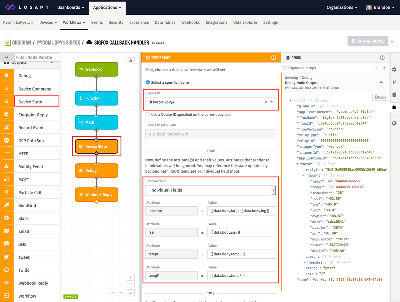
The Device State Node provides a way to record data onto our devices. In the node's configuration, make sure your Pycom device is selected. Next, using templates, set each attribute's value to their corresponding variable on the workflow payload. Below is a table of each attribute and their values:
| location | {{ data.body.lat }}, {{ data.body.lng }} |
| rssi | {{ data.body.rssi }} |
| tempC | {{ data.body.tempC }} |
| tempF | {{ data.body.tempF }} |
Most of these are pretty straightforward except for the location attribute. Losant understands a lot of different ways GPS data can be reported. In the example above, we're using a template to create a basic "<latitude>, <longitude>" string from the separate lat and lng values provided by Sigfox.
Once this workflow is saved, deployed, and data is received, we can verify data is recorded on the device by inspecting our device page's debug tab.
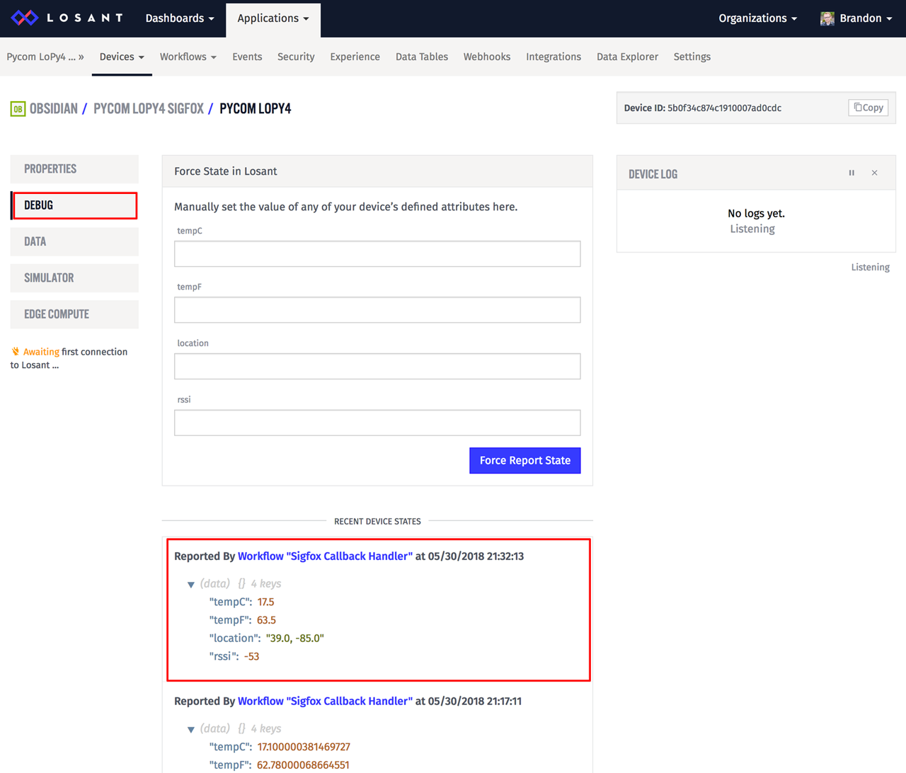
Under the "Recent Device States" section on the debug tab, you can see that data was successfully reported by our workflow.
How to Visualize Sigfox Data
At this point we're now successfully reading TMP36 sensor data, reporting to Sigfox, and storing that data on a Losant device. We can now use Losant's dashboard functionality to easily begin visualizing our Sigfox data.
First, create a new dashboard by clicking the main "Dashboards → Create Dashboard" menu item. You can name the dashboard anything you'd like.
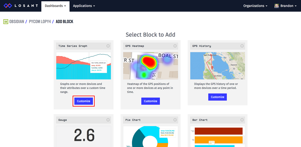
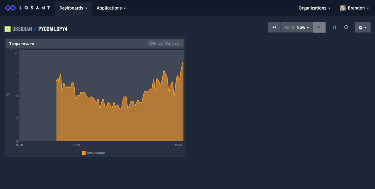
On the next screen, select the Time Series Graph as the first dashboard block to add. We'll use this to graph our temperature data.
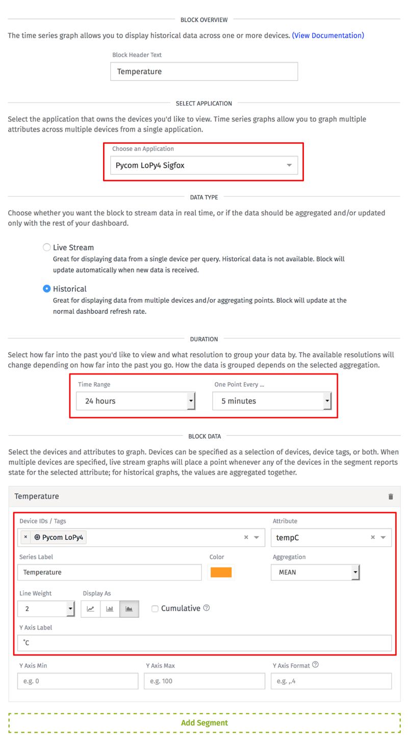
If you have more than one application, make sure the correct one is selected in the application drop down.
Next, set the time range and the resolution. The time range specifies how much data we'll graph. In the example above, it's set to 24 hours. The resolution determines how often a data point will be displayed. Since we're reporting data every 15 minutes, anything less than that means we'll see every data point. In the example above, it's set to 5 minutes.
Lastly, add a segment to your graph. Segments control which devices and attributes will be displayed. In this example, we're only going to graph the tempC attribute on our single device. The other settings are for display purposes only, so feel free to set them to anything you'd like.
After you click the "Add Block" button at the bottom, you'll see the new time series graph on your dashboard.
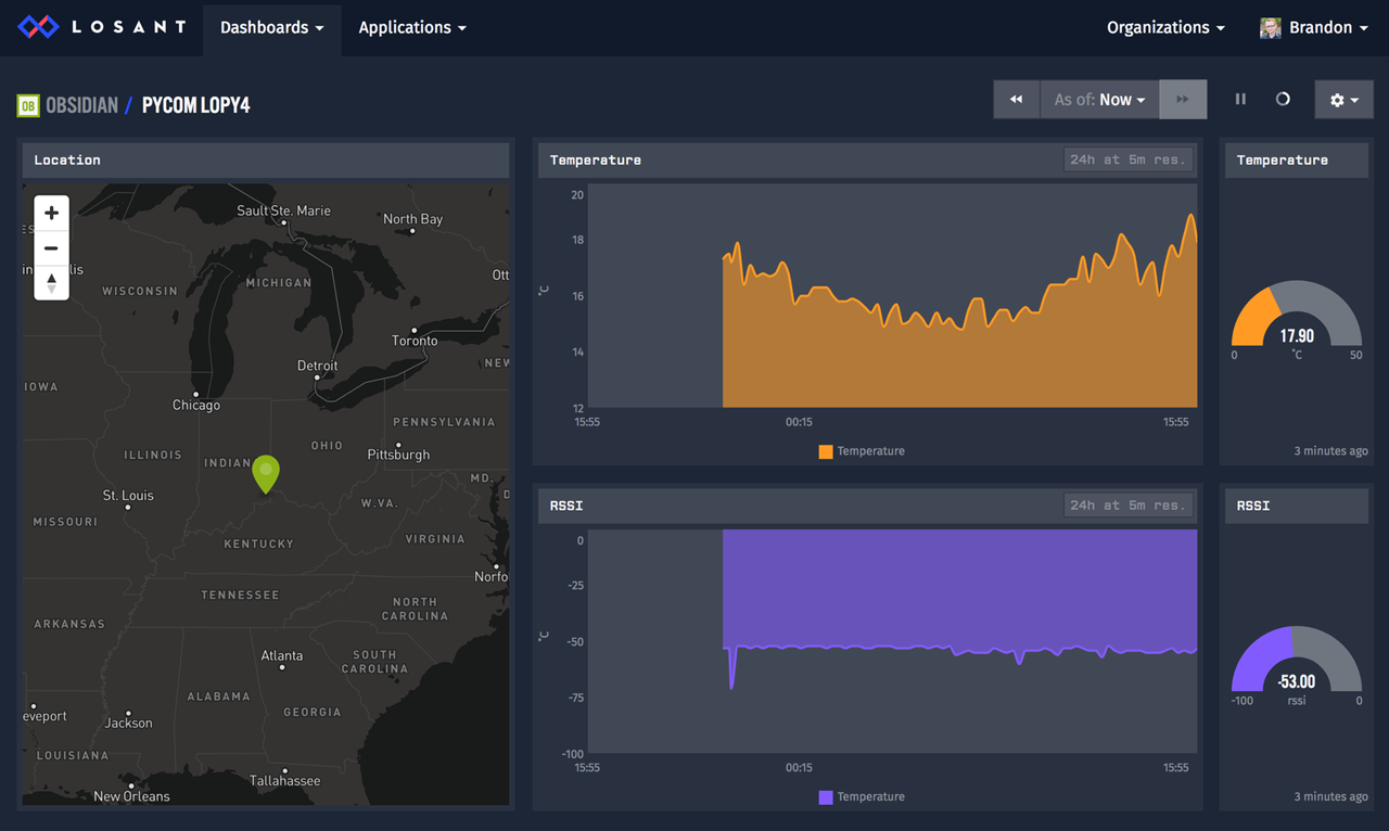
Feel free to explore the other dashboard block types, specifically the Gauge and GPS History blocks, to add additional information. Based on the information we're getting from our device and Sigfox, you could create a dashboard that looks like the following:
How to Send SMS Alerts for Sigfox Data
In the last part of this tutorial, we're going to send an SMS alert when the temperature exceeds a threshold. With Losant, this can easily be accomplished with another workflow. Create a new cloud workflow and name it anything you'd like.
Start by dragging a Device State Trigger on to the canvas.
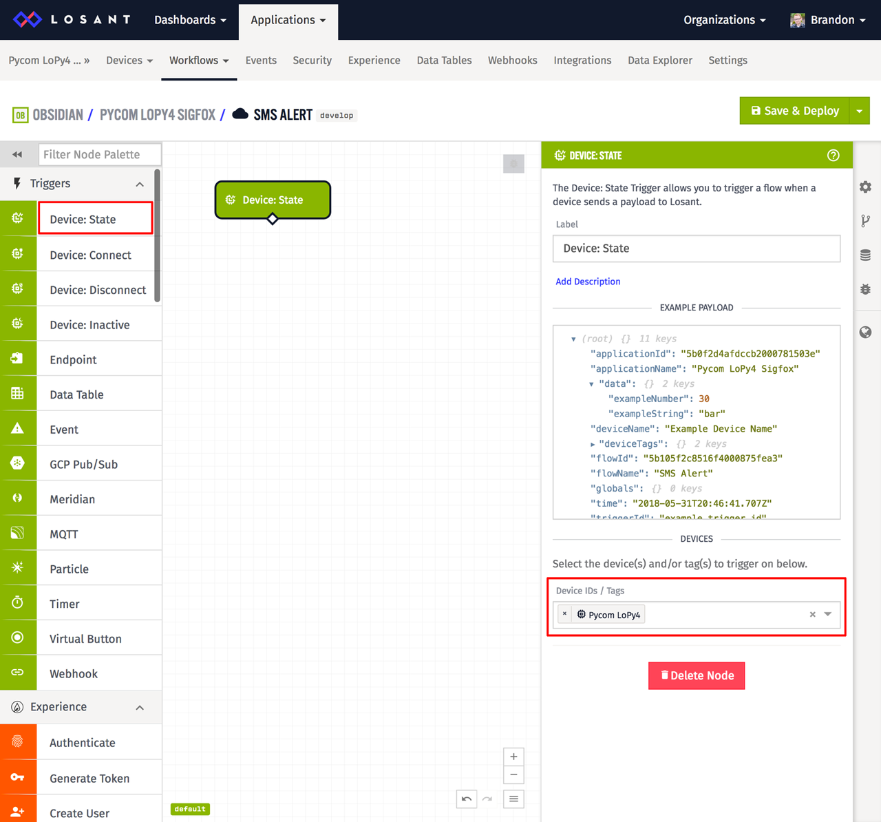
Configure the trigger to fire whenever state is reported for your Pycom device. In this application, state for your device is being reported by the other workflow that's handling Sigfox data. When that workflow reports state for your device, it will cause this workflow to trigger.
Next, add a Conditional Node that will check whether or not the temperature is above a threshold.
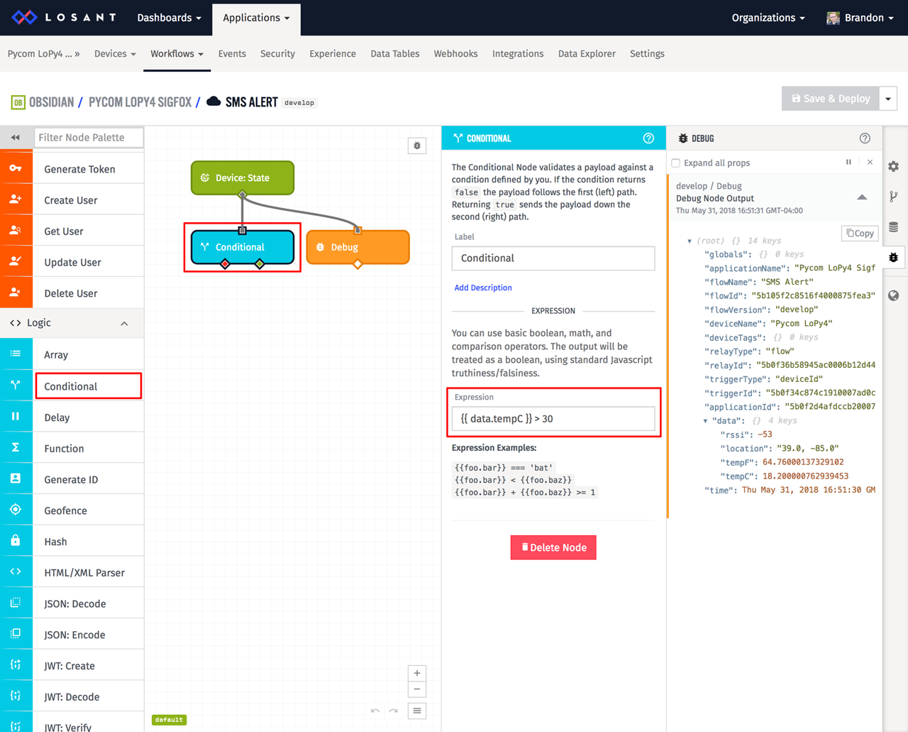
The Device State Trigger adds the reported state to the payload on the data object. This means if we want to check the tempC attribute that was reported, the condition expression is the following:
{{ data.tempC }} > 30
This expression will evaluate to true whenever our temperature exceeds 30 degrees Celsius. The Conditional Node has two outputs based on the expression's result. The left output executes when the expression evaluates to false. The right output executes when the expression evaluates to true.
Lastly, add an SMS Node and attach it to the right output on the Conditional Node.
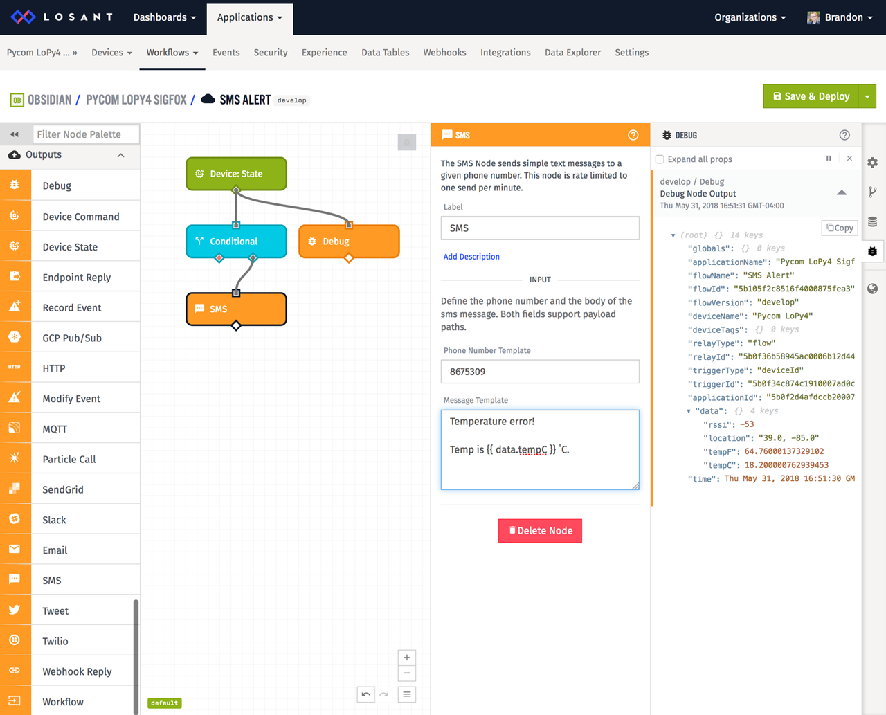
The SMS Node provides a way to send SMS messages to a phone number. Enter your desired phone number and message in the node's configuration. If you want, you can also use templates in the message so the actual data can be inserted into the message. The message in the above example is the following:
Temperature error!

Temp is {{ data.tempC }} ˚C.
Once this workflow is saved and deployed, whenever the temperature exceeds 30 degrees Celsius, you'll receive an SMS alert.
As an added challenge, feel free to expand this workflow to send Email or Slack notifications as well.
Build Something Awesome
At this point, you're successfully reading TMP36 sensor data with a Pycom LoPy4, transmitting to Sigfox, and visualizing and alerting on that data in Losant. This article is meant to provide a base level of understanding for how each of these tools work. It's now up to you to expand on what you've learned here to build something awesome.
If you want to take your application further, check out Losant's Experience functionality, which provides a way to build completely custom user interfaces on top of your devices, data, and users.
If you have many Sigfox devices, please read our other Sigfox guide, which includes instructions for on-demand device registration, which streamlines the integration even further.
If you have questions or used what you learned here in an amazing way, please let us know in the forums.